メインコンテンツにスキップ

このバージョンは誤った内容を含んでいる可能性があります。最新の承認済みスナップショットに切り替えてください。

必要な工具と部品

  1. この手順は未翻訳です。 翻訳を手伝う。

    : 手順 1、 2の画像 1 : 手順 1、 2の画像 2
    • Remove the five 3/8" screws from the base of the kettle using a Phillips #1 screwdriver.

  2. この手順は未翻訳です。 翻訳を手伝う。

    : 手順 2、 2の画像 1 : 手順 2、 2の画像 2
    • Using your hands, pry the base off the kettle.

    • Open the kettle like a clamshell; the ON/OFF switch will be the hinge point.

  3. この手順は未翻訳です。 翻訳を手伝う。

    : 手順 3、 3の画像 1 : 手順 3、 3の画像 2 : 手順 3、 3の画像 3
    • Using your hands, remove the kettle base by sliding it over the switch.

  4. この手順は未翻訳です。 翻訳を手伝う。

    : 手順 4、 1の画像 1
    • Now that you have removed the bottom from the kettle, identify all of the parts. The ORANGE arrows point to the posts for mounting the control circuit components. The RED arrows point to the following parts:

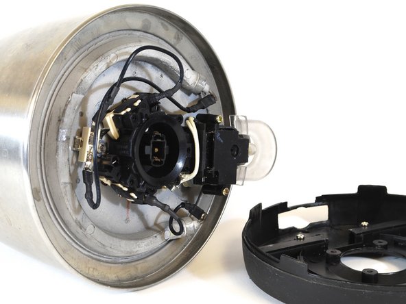
    • A: The power supply.

    • B: The two boil-dry protection switches, one on either side of the central black ring.

    • C: The power coupling. This fits into the baseplate when you place the kettle on it.

    • D: The thermostat. This is a little metal ring, half hidden by the switch cover.

    • E: The manual ON/OFF switch.

    • F: The indicator light.

    • G: The steam chamber. This heats the thermostat, which turns off the kettle automatically.

  5. この手順は未翻訳です。 翻訳を手伝う。

    : 手順 5、 3の画像 1 : 手順 5、 3の画像 2 : 手順 5、 3の画像 3
    • Take note of how the wires connect to the components to aid reassembly.

    • Remove the connectors (spaded lugs) from the circuit components as shown in the second image.

    • DO NOT pull on the wires, as you might pull them out of the connectors.

    • You should be able to remove each connector easily by hand. Pinch the lug between your fingers and pull in the direction of the attached wire.

    • If necessary, use needle-nose pliers to grasp the lug shank firmly. Gently pull the lug in the direction of the attached wire.

    • Gently bend the disconnected wires back and out of the work area.

  6. この手順は未翻訳です。 翻訳を手伝う。

    : 手順 6、 2の画像 1 : 手順 6、 2の画像 2
    この手順で使用する道具:
    Tweezers
    $4.99
    購入する
    • Using a 7/32" nut driver, remove the hex nut that secures the power supply to the base of the kettle.

    • Using a pair of tweezers, remove the split-ring lock washer located under the nut. (It may be hard to see in low light.)

  7. この手順は未翻訳です。 翻訳を手伝う。

    : 手順 7、 2の画像 1 : 手順 7、 2の画像 2
    • Using your hands, grasp the wire that is still connected to the power supply. Carefully lift the power supply off the threaded stud to which it was coupled.

    • At this point you will have removed the following parts from the kettle:

    • Five (5) screws.

    • The kettle base.

    • One (1) 7/32'' hex nut.

    • One (1) 7/32" split-ring lock washer.

    • One (1) power supply unit.

  8. この手順は未翻訳です。 翻訳を手伝う。

    : 手順 8、 2の画像 1 : 手順 8、 2の画像 2
    この手順で使用する道具:
    Tweezers
    $4.99
    購入する
    • FIRST IMAGE: Remove the power supply. Align the kettle as shown, with the handle to your right. Use the 7/32" nut driver to remove the 7/32" nut from the stud that is located clockwise from where the power supply was attached.

    • Use tweezers to remove the split-ring lock washer located under the nut.

    • SECOND IMAGE: Roll the kettle over so the handle is now on your left. Use the 7/32" nut driver to remove the 7/32" nut from the final stud, which is now located counter-clockwise from where the power supply was attached.

    • Use tweezers to remove the split-ring lock washer located under the nut.

  9. この手順は未翻訳です。 翻訳を手伝う。

    : 手順 9、 3の画像 1 : 手順 9、 3の画像 2 : 手順 9、 3の画像 3
    • Grasp the control switch with one hand and the kettle with the other.

    • Gently rock the control switch while simultaneously pulling it away from the bottom of the kettle.

    • Pull the switch completely off the kettle.

  10. この手順は未翻訳です。 翻訳を手伝う。

    : 手順 10、 1の画像 1
    • This image shows the alignment of various kettle parts.

    • The yellow arrows show how the studs align with the switch brackets.

    • The blue arrow shows how the steam tube aligns with the steam chamber on the switch thermostat.

ゴール

8 の人々がこのガイドを完成させました。

作成者

6人の作成者と共同で作成されました。

Randy Fromm

メンバー登録日: 01/22/14

565 ポイント

3のガイドは作成済み

チーム

New Mexico State, Team 1-1, Sheppard Spring 2014 New Mexico State, Team 1-1, Sheppard Spring 2014人のメンバー

NMSU-SHEPPARD-S14S1G1

4 メンバー

3のガイドは作成済み

コメント 1 件

OK, now I can look from the bottom. But why the switch does not keep down when I press it down I can not see or repair.

Robert

Robert Wallnig - 返信

コメントを追加

統計データ:

過去 24時間: 3

過去 7 日: 19

過去 30 日: 69

今までの合計 5,731