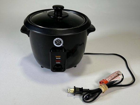
メインコンテンツにスキップ

Chef’s Counter Rice Cooker RC-3 Disassembly

必要な工具と部品

  1. Chef’s Counter Rice Cooker RC-3 Disassembly, Chef’s Counter Rice Cooker RC-3: 手順 1、 3の画像 1 Chef’s Counter Rice Cooker RC-3 Disassembly, Chef’s Counter Rice Cooker RC-3: 手順 1、 3の画像 2 Chef’s Counter Rice Cooker RC-3 Disassembly, Chef’s Counter Rice Cooker RC-3: 手順 1、 3の画像 3
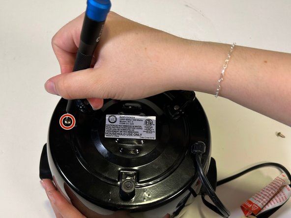
    • Unplug the rice cooker.

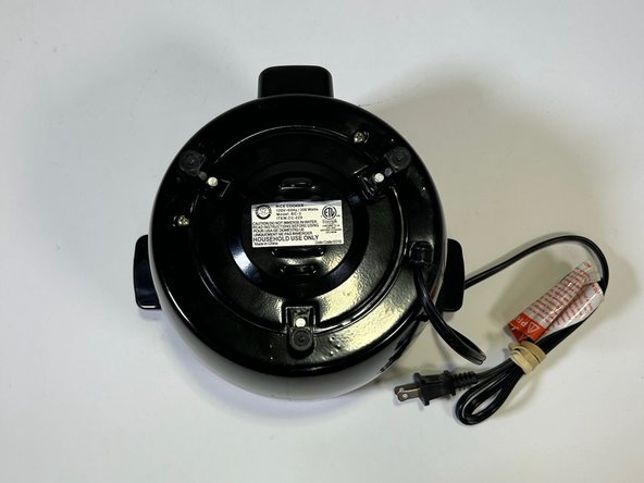
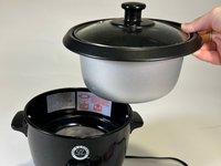
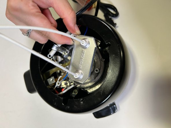
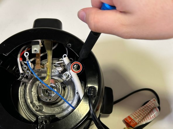
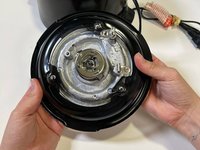
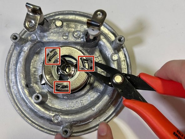
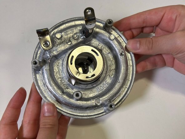
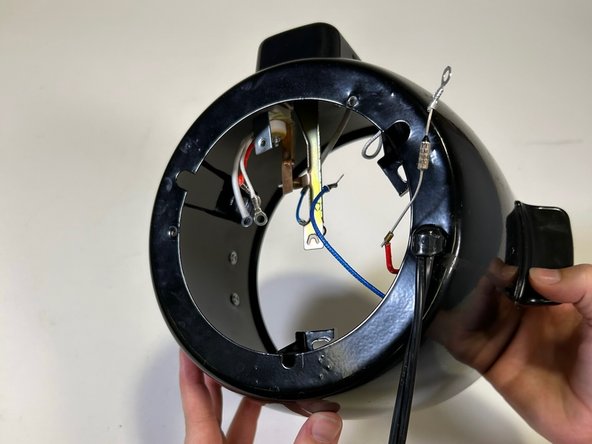
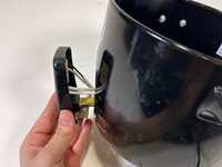
    • Remove the bowl and lid from the device and place the device upside down on a flat surface.

  2. Chef’s Counter Rice Cooker RC-3 Disassembly: 手順 2、 3の画像 1 Chef’s Counter Rice Cooker RC-3 Disassembly: 手順 2、 3の画像 2 Chef’s Counter Rice Cooker RC-3 Disassembly: 手順 2、 3の画像 3
    • Remove the two 13 mm screws from the bottom using a Phillips #1 screwdriver.

    • Remove the base plate.

  3. Chef’s Counter Rice Cooker RC-3 Disassembly: 手順 3、 3の画像 1 Chef’s Counter Rice Cooker RC-3 Disassembly: 手順 3、 3の画像 2 Chef’s Counter Rice Cooker RC-3 Disassembly: 手順 3、 3の画像 3
    • Remove the three 10 mm gold screws holding the wires in place using a Phillips #1 screwdriver.

  4. Chef’s Counter Rice Cooker RC-3 Disassembly: 手順 4、 3の画像 1 Chef’s Counter Rice Cooker RC-3 Disassembly: 手順 4、 3の画像 2 Chef’s Counter Rice Cooker RC-3 Disassembly: 手順 4、 3の画像 3
    • Remove the single 10 mm screw from the metal plate using a Phillips #1 screwdriver.

    • Remove the metal plate.

  5. Chef’s Counter Rice Cooker RC-3 Disassembly: 手順 5、 3の画像 1 Chef’s Counter Rice Cooker RC-3 Disassembly: 手順 5、 3の画像 2 Chef’s Counter Rice Cooker RC-3 Disassembly: 手順 5、 3の画像 3
    • Remove the three perimeter screws holding the heating plate in place using a Phillips #1 screwdriver.

    • One screw has a length of 14 mm and two screws are 10 mm.

  6. Chef’s Counter Rice Cooker RC-3 Disassembly: 手順 6、 3の画像 1 Chef’s Counter Rice Cooker RC-3 Disassembly: 手順 6、 3の画像 2 Chef’s Counter Rice Cooker RC-3 Disassembly: 手順 6、 3の画像 3
    • Use pliers to pinch the metal V in the center.

    • Slide out the silver heating component and black support ring.

  7. Chef’s Counter Rice Cooker RC-3 Disassembly: 手順 7、 3の画像 1 Chef’s Counter Rice Cooker RC-3 Disassembly: 手順 7、 3の画像 2 Chef’s Counter Rice Cooker RC-3 Disassembly: 手順 7、 3の画像 3
    • Use the pliers to pinch the three metal flaps flat and remove the spring.

  8. Chef’s Counter Rice Cooker RC-3 Disassembly: 手順 8、 2の画像 1 Chef’s Counter Rice Cooker RC-3 Disassembly: 手順 8、 2の画像 2
    • Remove the metal hook that is over the thick white wire cover.

  9. Chef’s Counter Rice Cooker RC-3 Disassembly: 手順 9、 2の画像 1 Chef’s Counter Rice Cooker RC-3 Disassembly: 手順 9、 2の画像 2
    • Remove the thick white wire cover uncovering the thermal cutoff fuse.

  10. Chef’s Counter Rice Cooker RC-3 Disassembly: 手順 10、 2の画像 1 Chef’s Counter Rice Cooker RC-3 Disassembly: 手順 10、 2の画像 2
    • Flip over the rice cooker so it is right side up.

  11. Chef’s Counter Rice Cooker RC-3 Disassembly: 手順 11、 3の画像 1 Chef’s Counter Rice Cooker RC-3 Disassembly: 手順 11、 3の画像 2 Chef’s Counter Rice Cooker RC-3 Disassembly: 手順 11、 3の画像 3
    • Remove the single 10 mm screw from the outer control panel using a Phillips #1 screwdriver.

    • Remove the plastic outer control panel.

  12. Chef’s Counter Rice Cooker RC-3 Disassembly: 手順 12、 3の画像 1 Chef’s Counter Rice Cooker RC-3 Disassembly: 手順 12、 3の画像 2 Chef’s Counter Rice Cooker RC-3 Disassembly: 手順 12、 3の画像 3
    • Remove the single 10 mm screw using a Phillips #1 screwdriver to reveal the LED lights.

  13. Chef’s Counter Rice Cooker RC-3 Disassembly: 手順 13、 3の画像 1 Chef’s Counter Rice Cooker RC-3 Disassembly: 手順 13、 3の画像 2 Chef’s Counter Rice Cooker RC-3 Disassembly: 手順 13、 3の画像 3
    • Remove the single 27 mm screw using a hex 5.5 screwdriver.

    • Extra hands are helpful because this component will easily fall apart.

  14. Chef’s Counter Rice Cooker RC-3 Disassembly: 手順 14、 2の画像 1 Chef’s Counter Rice Cooker RC-3 Disassembly: 手順 14、 2の画像 2
    • Inspect the outer control panel, mechanical lever, and the components of the stack.

  15. Chef’s Counter Rice Cooker RC-3 Disassembly: 手順 15、 1の画像 1
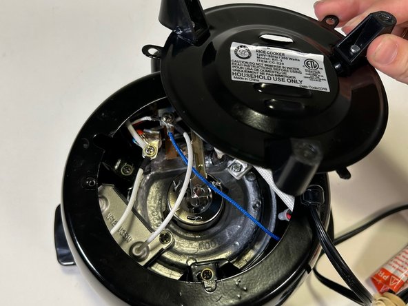
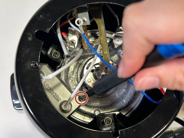
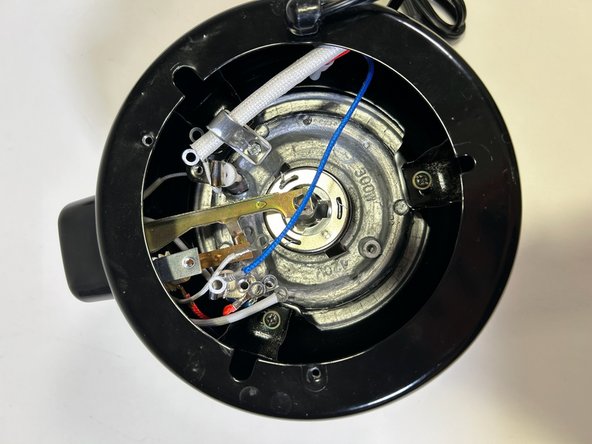
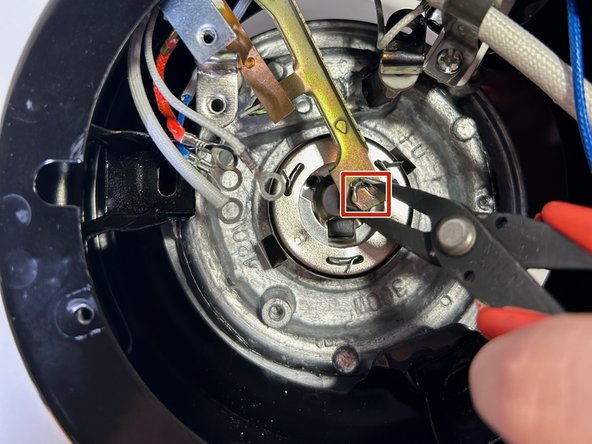
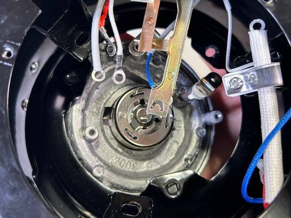
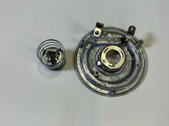
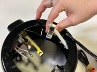
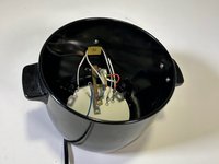
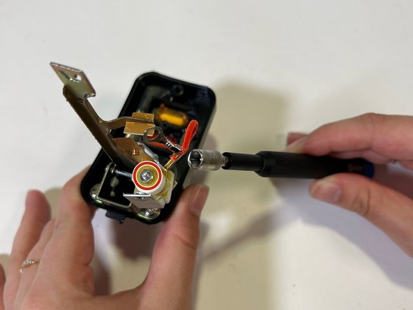
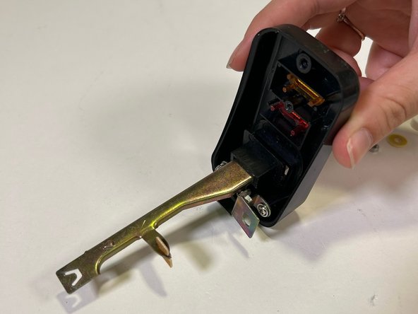
    • Now that the device is disassembled you can get a better understanding on how it works.

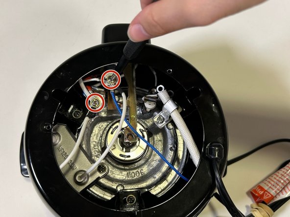
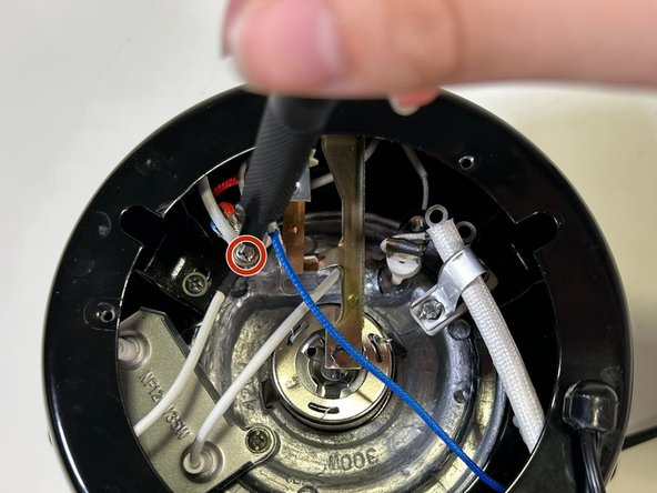
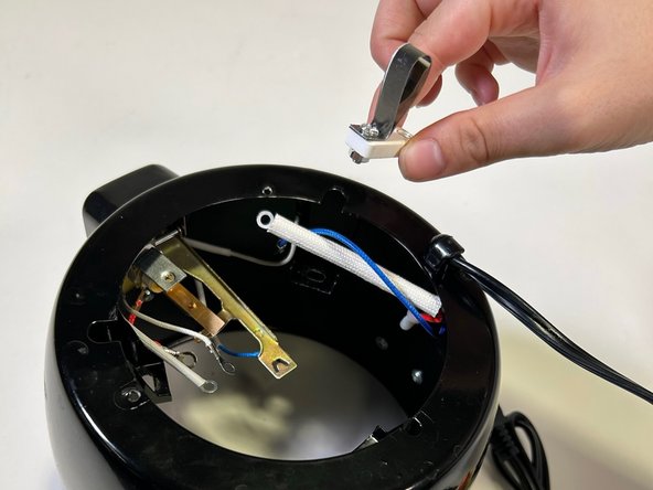
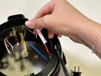
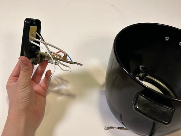
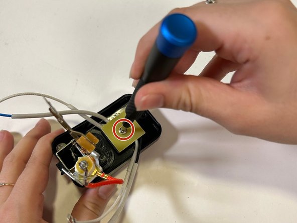
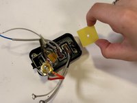
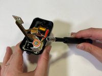
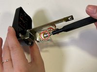
    • The rice cooker receives constant power when plugged in. A mechanical lever is used to switch between warm and cook settings. The settings are indicated by white LED lights with orange and red plastic coverings on the outer control panel.

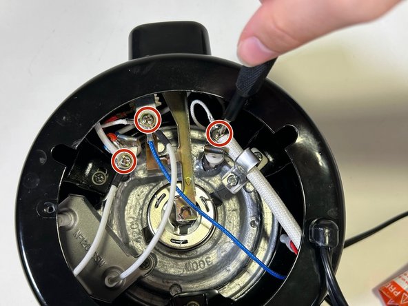
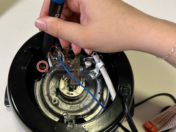
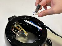
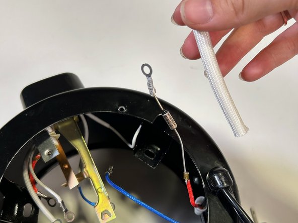
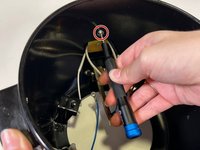
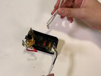
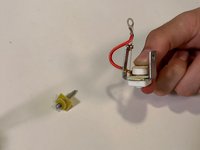
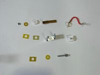
    • A DF184S Thermal Cutoff Fuse is in place to protect the device by disconnecting the circuit in the event of a heating element malfunction.

終わりに

To reassemble your device, follow these instructions in reverse order.

作成者

1人の作成者と共同作成されました。

Korinna Spirko

メンバー登録日: 09/10/24

291 ポイント

1ガイドが承認済み

チーム

0件のガイドコメント

コメントを追加

統計データ:

過去 24時間: 1

過去 7 日: 2

過去 30 日: 17

今までの合計 200