メインコンテンツにスキップ

このバージョンは誤った内容を含んでいる可能性があります。最新の承認済みスナップショットに切り替えてください。

必要な工具と部品

  1. この手順は未翻訳です。 翻訳を手伝う。

    : 手順 1、 1の画像 1
    • Lay the device on its back, and rotate so the base is facing away from you.

  2. この手順は未翻訳です。 翻訳を手伝う。

    : 手順 2、 1の画像 1
    • Grip the frame with your fingers under the edge of the frame, and thumbs pushing down on the front of the device.

  3. この手順は未翻訳です。 翻訳を手伝う。

    : 手順 3、 1の画像 1
    • Lift up the frame with your fingers and push down the rest of the device with your thumbs.

  4. この手順は未翻訳です。 翻訳を手伝う。

    : 手順 4、 1の画像 1
    • Remove the frame and matte from the device.

  5. この手順は未翻訳です。 翻訳を手伝う。

    : 手順 5、 1の画像 1
    • Remove the four 7mm Torx T6 screws.

  6. この手順は未翻訳です。 翻訳を手伝う。

    : 手順 6、 2の画像 1 : 手順 6、 2の画像 2
    • Using the plastic opening tool or your fingers, lift up the frame from any edge.

    • Remove the frame from the device.

  7. この手順は未翻訳です。 翻訳を手伝う。

    : 手順 7、 3の画像 1 : 手順 7、 3の画像 2 : 手順 7、 3の画像 3
    • Unplug the cable connecting the display to the power supply using the flat end of the spudger to pry the connector away from the circuit board.

    • Alternate applying pressure to the left and right side of the connector to ensure that it does not break.

  8. この手順は未翻訳です。 翻訳を手伝う。

    : 手順 8、 1の画像 1
    • Remove the four 7mm Torx T6 screws.

  9. この手順は未翻訳です。 翻訳を手伝う。

    : 手順 9、 2の画像 1 : 手順 9、 2の画像 2
    • Lift up the display from the left edge and flip display over.

    • Do not lift the display too quickly, as the display is still connected to the main circuit board on the right.

  10. この手順は未翻訳です。 翻訳を手伝う。

    : 手順 10、 3の画像 1 : 手順 10、 3の画像 2 : 手順 10、 3の画像 3
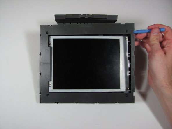
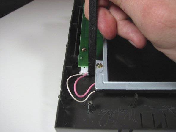
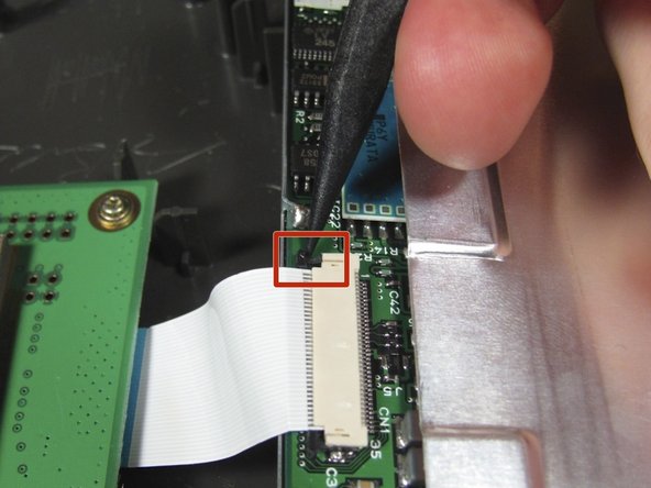
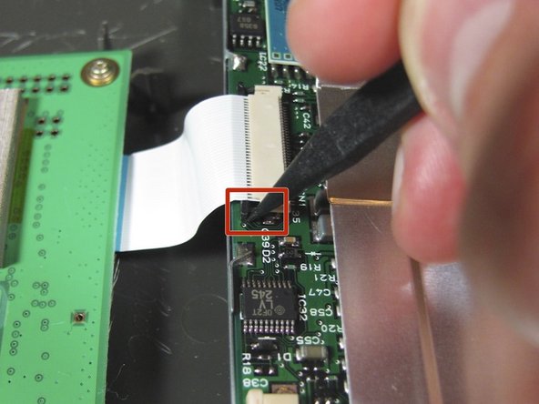
    • Use the spudger to disconnect the ribbon cable from the display by the black pins away from the connector. There is a pin on either side of the connector.

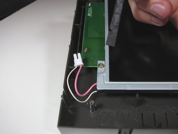
    • Once both pins are released, the ribbon cable should slide easily out.

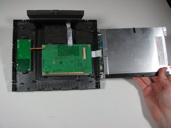
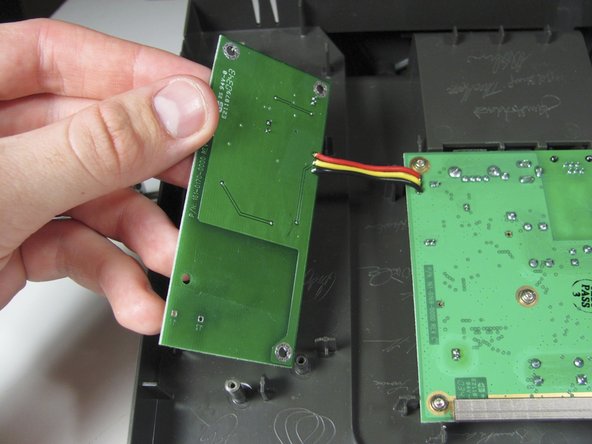
    • It may be easier if someone else holds the display so the cable does not get ripped out.

  11. この手順は未翻訳です。 翻訳を手伝う。

    : 手順 11、 1の画像 1
    • Remove the display assembly from the device.

  12. この手順は未翻訳です。 翻訳を手伝う。

    : 手順 12、 1の画像 1
    • Remove the four 7mm Torx T6 screws.

  13. この手順は未翻訳です。 翻訳を手伝う。

    : 手順 13、 2の画像 1 : 手順 13、 2の画像 2
    • Desolder the 3 wires attached to the board.

    • Remove the power supply board from the device.

    • The wires shown were not actually desoldered, but the board will now be separated from the rest of the device.

ゴール

ある他の人がこのガイドを完成しました。

作成者

2人の作成者と共同で作成されました。

Casey Glasgow

メンバー登録日: 01/26/14

510 ポイント

5のガイドは作成済み

チーム

Cal Poly, Team 9-25, Maness Winter 2014 Cal Poly, Team 9-25, Maness Winter 2014人のメンバー

CPSU-MANESS-W14S9G25

4 メンバー

5のガイドは作成済み

0 件のコメント

コメントを追加

統計データ:

過去 24時間: 0

過去 7 日: 6

過去 30 日: 13

今までの合計 155