メインコンテンツにスキップ

Cardinal Health Vela Ventilator Turbine/Muffler Assembly P/N 16349 Replacement

医療機器
この修理ガイドは医療機器メーカーからの是認を得ておらず、iFixitと医療機器メーカーは提携していません。

必要な工具と部品

  1. 注意: 手順 1-2 は、作業進行中としてマークされている ガイド から引用されています。

    Cardinal Health Vela Ventilator Turbine/Muffler Assembly P/N 16349 Replacement, Cardinal Health Vela Ventilator Power Cable Removal: 手順 1、 1の画像 1
    • Use a screwdriver to remove the two Phillips pan-head screws at the top of the plug guard.

    • Remove the plug guard and unplug the ventilator.

  2. Cardinal Health Vela Ventilator Turbine/Muffler Assembly P/N 16349 Replacement, Cardinal Health Vela Ventilator Top Cover Disassembly: 手順 3、 1の画像 1
    • Remove the four Phillips #0 screws on the back side of the ventilator.
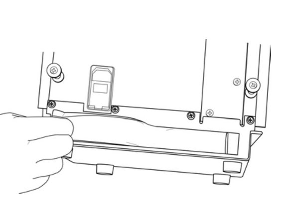
  3. Cardinal Health Vela Ventilator Turbine/Muffler Assembly P/N 16349 Replacement: 手順 4、 1の画像 1
    • Remove all six small side panel screws along the bottom of each side of the top cover with the same screwdriver.

    • Slide the top cover towards the back side of the ventilator to remove it.

  4. 注意: 手順 6-8 は、作業進行中としてマークされている ガイド から引用されています。

    Cardinal Health Vela Ventilator Turbine/Muffler Assembly P/N 16349 Replacement, Cardinal Health Vela Ventilator Battery Tray Removal: 手順 6、 1の画像 1
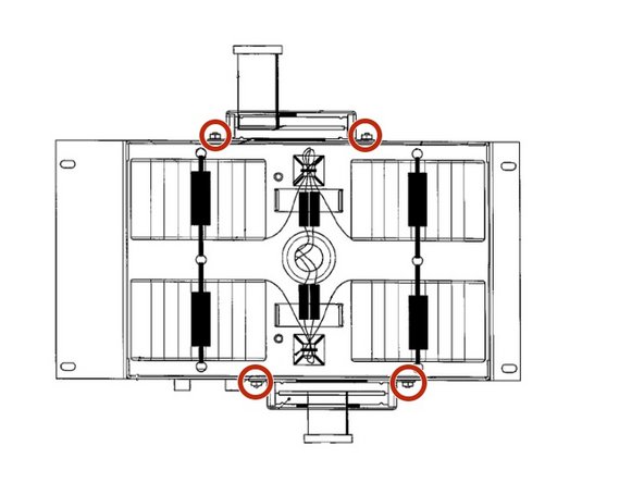
    • Use your Phillips screwdriver to unscrew the 4 Phillips pan head screws positioned on each side of the battery tray.
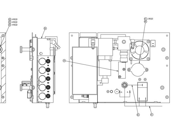
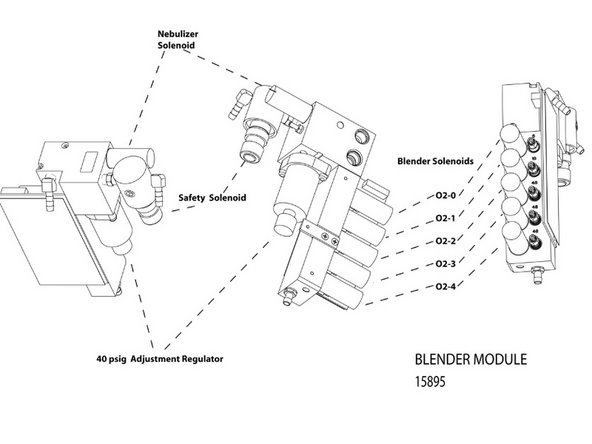
    • Lift the battery tray out of the ventilator.

    • Caution: The wires connecting the batteries to the ventilator will still be connected so lift the battery tray carefully.

  5. Cardinal Health Vela Ventilator Turbine/Muffler Assembly P/N 16349 Replacement: 手順 8、 1の画像 1
    • Disconnect the batteries from the ventilator by pulling apart the Battery Connector.

    • Remove the two Phillips countersink at the rear of the panel.

    • Remove the Phillips countersink in the upper front of the panel.

    • The panel is now free and can be lifted from the device.

    • To install the left panel follow these steps in reverse order.

  6. 注意: 手順 13-21 は、作業進行中としてマークされている ガイド から引用されています。

    Cardinal Health Vela Ventilator Turbine/Muffler Assembly P/N 16349 Replacement, Blender Assembly P/N 16358A: 手順 13、 1の画像 1
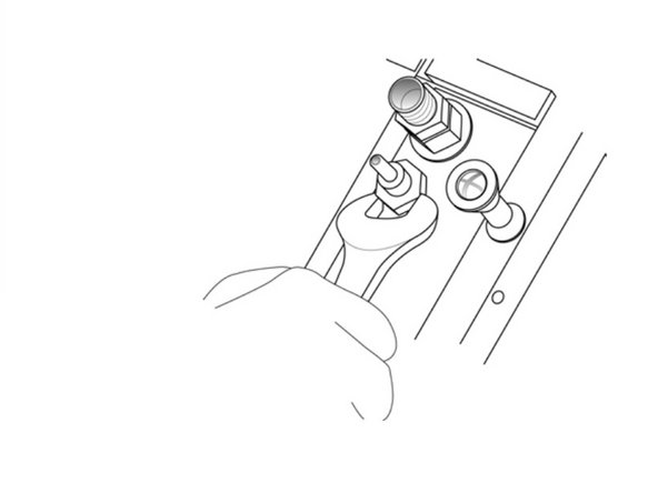
    • If the rear panel is installed, remove the high and low pressure oxygen fittings from the rear panel using your 3/4" wrench. NOTE: the high pressure fitting is located above the low pressure fitting

    • If the rear panel is installed, disconnect the 40-pin ribbon cable from the SVGA out PCB.

  7. Cardinal Health Vela Ventilator Turbine/Muffler Assembly P/N 16349 Replacement: 手順 15、 1の画像 1
    • If the front panel is installed, disconnect the green oxygen nebulizer tube.

    • Disconnect the:

    • -J301, 12-Pin Connector to J301 on the main PCB

    • From the blender PCB

  8. Cardinal Health Vela Ventilator Turbine/Muffler Assembly P/N 16349 Replacement: 手順 17、 1の画像 1
    • Remove the bottom strip ambient air inlet filter by pinching and pulling it out.

  9. Cardinal Health Vela Ventilator Turbine/Muffler Assembly P/N 16349 Replacement: 手順 18、 1の画像 1
    • Remove the three Phillips pan-head screws on the right side of the rear panel.

  10. Cardinal Health Vela Ventilator Turbine/Muffler Assembly P/N 16349 Replacement: 手順 19、 1の画像 1
    • The assembly should now be free to remove. As you remove the unit use your needle-nose pliers to disconnect the oxygen diffuser tube as you remove the blender assembly.

  11. Cardinal Health Vela Ventilator Turbine/Muffler Assembly P/N 16349 Replacement: 手順 20、 2の画像 1 Cardinal Health Vela Ventilator Turbine/Muffler Assembly P/N 16349 Replacement: 手順 20、 2の画像 2
    • If the exhalation valve assembly is installed, disconnect:

    • J3 [2-pin (blue connection)]

    • To the oxygen inlet solenoid on the blender assembly.

    • J4 [2-pin (red connection)]

    • To the Nebulizer solenoid assembly on upper rear of blender.

    • For Instillation follow steps in reverse order.

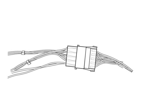
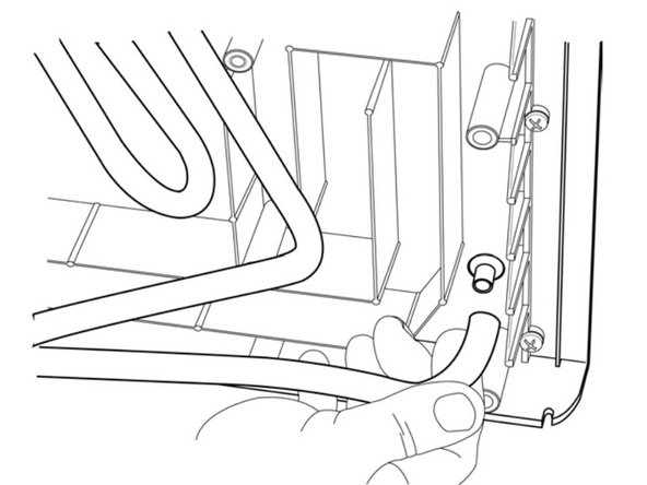
    • Disconnect the main wire harness connector at P2 on the Turbine Driver PCBA

  12. Cardinal Health Vela Ventilator Turbine/Muffler Assembly P/N 16349 Replacement: 手順 23、 1の画像 1
    • Remove the 5 Phillips pan-head mounting screws.

    • Disconnect the gray silicone intake and output elbows by gently pulling them out from the muffler tubes.

    • The Turbine/Muffler Assembly should now be free to lift off the manifold base.

    • Gently pull up on the elbows to remove

    • To Install P/N 16350 "Turbine/Muffler Assembly" repeat the steps in reverse order.

終わりに

To reassemble your device, follow these instructions in reverse order.

ある他の人がこのガイドを完成しました。

作成者

1人の作成者と共同作成されました。

Tanner Hillman

メンバー登録日: 04/10/20

370 ポイント

3のガイドは作成済み

チーム

Cal Poly, Team S7-G22, Paton Spring 2020 Cal Poly, Team S7-G22, Paton Spring 2020人のメンバー

CPSU-PATON-S20S7G22

1 メンバー

3のガイドは作成済み

0 件のコメント

コメントを追加

統計データ:

過去 24時間: 0

過去 7 日: 0

過去 30 日: 1

今までの合計 280