メインコンテンツにスキップ

Canon ZR70MC LCD Component Replacement

必要な工具と部品

  1. Canon ZR70MC LCD Component Replacement, Front Panel: 手順 1、 2の画像 1 Canon ZR70MC LCD Component Replacement, Front Panel: 手順 1、 2の画像 2
    • Unscrew the 3.35mm screw.

  2. Canon ZR70MC LCD Component Replacement: 手順 2、 1の画像 1
    • Turn the ZR70MC so that you can see the bottom of the camcorder.

    • Unscrew the 3.35 mm located in the top left portion of the camera.

  3. Canon ZR70MC LCD Component Replacement: 手順 3、 3の画像 1 Canon ZR70MC LCD Component Replacement: 手順 3、 3の画像 2 Canon ZR70MC LCD Component Replacement: 手順 3、 3の画像 3
    • Turn the camera on the side and remove the cover for the audio inputs. There is a 2.65 mm screw located behind the cover.

    • Remove the 2.65 mm screw.

  4. Canon ZR70MC LCD Component Replacement: 手順 4、 3の画像 1 Canon ZR70MC LCD Component Replacement: 手順 4、 3の画像 2 Canon ZR70MC LCD Component Replacement: 手順 4、 3の画像 3
    • Remove the cover located on the front of the camcorder and remove the cover by pulling on the bottom groove.

    • Locate and remove the two 3.35 mm screws.

  5. Canon ZR70MC LCD Component Replacement: 手順 5、 2の画像 1 Canon ZR70MC LCD Component Replacement: 手順 5、 2の画像 2
    • Turn the camcorder so that the bottom is facing up and open the tape cassette compartment.

    • There is one 3.35 mm screw located under the tape cassette panel on the front left side of the camcorder. Remove the screw.

  6. Canon ZR70MC LCD Component Replacement: 手順 6、 3の画像 1 Canon ZR70MC LCD Component Replacement: 手順 6、 3の画像 2 Canon ZR70MC LCD Component Replacement: 手順 6、 3の画像 3
    • Now that all of the screws are removed, remove the front panel by gently pulling on the front panel.

    • The speaker will be connected to the main body by a wire. Be careful not to damage this wire.

  7. Canon ZR70MC LCD Component Replacement: 手順 7、 3の画像 1 Canon ZR70MC LCD Component Replacement: 手順 7、 3の画像 2 Canon ZR70MC LCD Component Replacement: 手順 7、 3の画像 3
    • Use tweezers to gently pull the speaker wire from the main body of the camcorder.

    • Pull the front panel completely away from the main body of the camcorder.

  8. Canon ZR70MC LCD Component Replacement, LCD screen: 手順 8、 3の画像 1 Canon ZR70MC LCD Component Replacement, LCD screen: 手順 8、 3の画像 2 Canon ZR70MC LCD Component Replacement, LCD screen: 手順 8、 3の画像 3
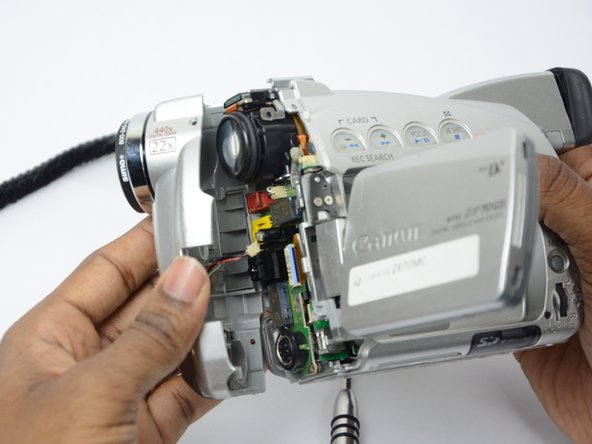
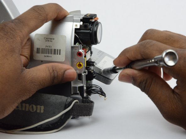
    • Open the LCD screen.

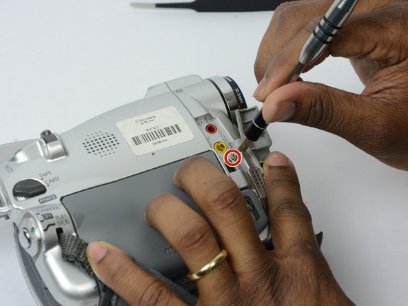
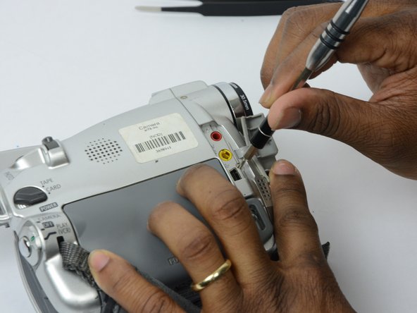
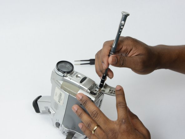
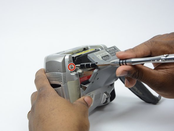
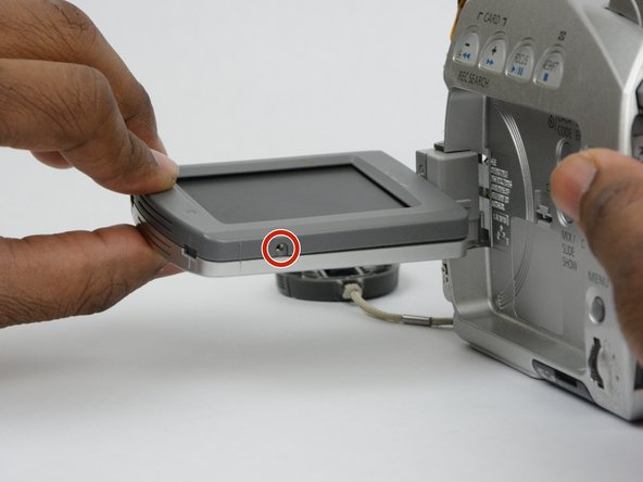
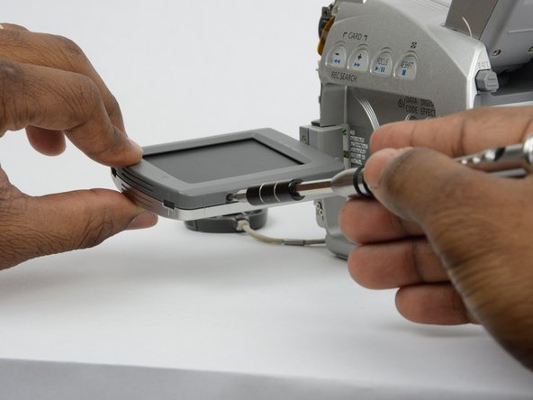
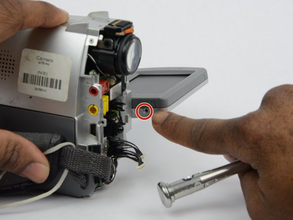
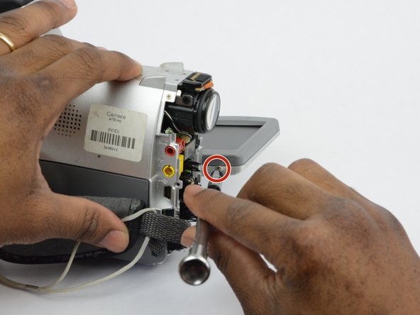
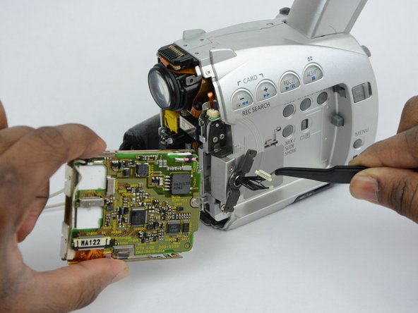
    • Locate and remove the 2.7 mm screw on the bottom of the LCD monitor.

  9. Canon ZR70MC LCD Component Replacement: 手順 9、 3の画像 1 Canon ZR70MC LCD Component Replacement: 手順 9、 3の画像 2 Canon ZR70MC LCD Component Replacement: 手順 9、 3の画像 3
    • Turn the LCD monitor so that the screen is facing down.

    • There is a 2.7 mm screw on the LCD monitor where the monitor is connected to the main body of the camcorder. Remove the 2.7 mm screw.

  10. Canon ZR70MC LCD Component Replacement: 手順 10、 2の画像 1 Canon ZR70MC LCD Component Replacement: 手順 10、 2の画像 2
    • Turn the LCD monitor so that the screen is facing up.

    • There is a 2.7 mm screw located where the LCD monitor is connected to the main body of the camcorder. Remove the 2.7 mm screw.

  11. Canon ZR70MC LCD Component Replacement: 手順 11、 3の画像 1 Canon ZR70MC LCD Component Replacement: 手順 11、 3の画像 2 Canon ZR70MC LCD Component Replacement: 手順 11、 3の画像 3
    • Now that all the screws are removed, use the plastic opening tool to gently pry the LCD monitor case open.

  12. Canon ZR70MC LCD Component Replacement: 手順 12、 3の画像 1 Canon ZR70MC LCD Component Replacement: 手順 12、 3の画像 2 Canon ZR70MC LCD Component Replacement: 手順 12、 3の画像 3
    • Use tweezers to remove the wire connections that hold the LCD screen in place.

    • Remove the entire LCD screen.

終わりに

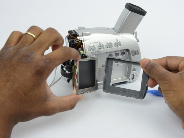
To reassemble your device, follow these instructions in reverse order.

ある他の人がこのガイドを完成しました。

作成者

3人の作成者と共同で作成されました。

khalid clarke

メンバー登録日: 09/26/17

824 ポイント

7のガイドは作成済み

チーム

USF Tampa, Team S13-G2, Boczar Fall 2017 USF Tampa, Team S13-G2, Boczar Fall 2017人のメンバー

USFT-BOCZAR-F17S13G2

3 メンバー

14のガイドは作成済み

0 件のコメント

コメントを追加

統計データ:

過去 24時間: 0

過去 7 日: 0

過去 30 日: 1

今までの合計 166