メインコンテンツにスキップ

このバージョンは誤った内容を含んでいる可能性があります。最新の承認済みスナップショットに切り替えてください。

必要な工具と部品

  1. この手順は未翻訳です。 翻訳を手伝う。

    : 手順 1、 1の画像 1
    • Turn off the camera by pressing the power button above the LCD screen.

  2. この手順は未翻訳です。 翻訳を手伝う。

    : 手順 2、 1の画像 1
    • Remove the two, small screws on the bottom of the camera using a Phillip's #00 screwdriver.

  3. この手順は未翻訳です。 翻訳を手伝う。

    : 手順 3、 1の画像 1
    • Use a Phillips #00 screwdriver to remove the two, small screws on the right side of the camera.

  4. この手順は未翻訳です。 翻訳を手伝う。

    : 手順 4、 1の画像 1
    • Use a Phillips #00 screwdriver to remove the screw on the left of the camera under the A/V out Digital label.

  5. この手順は未翻訳です。 翻訳を手伝う。

    : 手順 5、 1の画像 1
    • Use a Phillips #00 screwdriver, remove the screw on the bottom of the camera near the battery and memory card slots.

    • This screw will be longer than the rest of the screws.

  6. この手順は未翻訳です。 翻訳を手伝う。

    : 手順 6、 1の画像 1
    • Remove the front, back, and side casings from the camera and set to the side.

  7. この手順は未翻訳です。 翻訳を手伝う。

    : 手順 7、 1の画像 1
    • Once the LCD and Backlight are detached, remove the larger screw marked in red in the picture as well as the four smaller sized screws marked in blue.

  8. この手順は未翻訳です。 翻訳を手伝う。

    : 手順 8、 1の画像 1
    • Remove the two screws near the the tri-pod mount with a Philips head screw driver.

  9. この手順は未翻訳です。 翻訳を手伝う。

    : 手順 9、 1の画像 1
    • Remove the screw next to the shutter with a Philip's head screw driver.

  10. この手順は未翻訳です。 翻訳を手伝う。

    : 手順 10、 1の画像 1
    • Remove the orange ribbon cable by lifting the ZIF connector attached to the ribbon with a flat head screw driver or spudger.

  11. この手順は未翻訳です。 翻訳を手伝う。

    : 手順 11、 2の画像 1 : 手順 11、 2の画像 2
    • Carefully lift the shutter along with the ribbon connected to it. This will remove the casing around the motherboard.

  12. この手順は未翻訳です。 翻訳を手伝う。

    : 手順 12、 3の画像 1 : 手順 12、 3の画像 2 : 手順 12、 3の画像 3
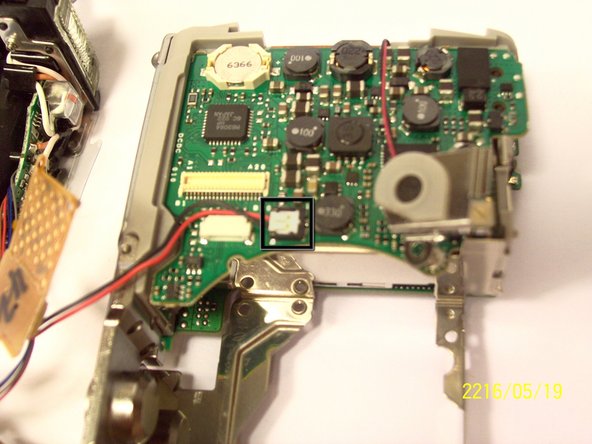
    • With the motherboard casing detached, remove the short orange ribbon by lifting the ZIF connector with a spudger or other plastic opening tools and slide the ribbon out. Detaching this ribbon will disconnect the side of the camera containing the motherboard from the rest of the camera.

  13. この手順は未翻訳です。 翻訳を手伝う。

    : 手順 13、 2の画像 1 : 手順 13、 2の画像 2
    • First remove the wires that are attached to the motherboard, as shown by the black box. You can detach them by simply pulling them out.

    • Next you can remove the film by lifting it gently from the motherboard.

  14. この手順は未翻訳です。 翻訳を手伝う。

    : 手順 14、 1の画像 1
    • Remove the last wires connected to the motherboard. You can remove it by gently lifting it upwards.

  15. この手順は未翻訳です。 翻訳を手伝う。

    : 手順 15、 2の画像 1 : 手順 15、 2の画像 2
    • Place a flathead screwdriver and gently lift the circuit attached, as shown on the picture.

  16. この手順は未翻訳です。 翻訳を手伝う。

    : 手順 16、 2の画像 1 : 手順 16、 2の画像 2
    • Remove the screw using a philip 00 screwdriver.

    • Once the screw is removed, gently lift the motherboard away from the case.

  17. この手順は未翻訳です。 翻訳を手伝う。

    : 手順 17、 2の画像 1 : 手順 17、 2の画像 2
    • Remove the screw as shown by the red circle.

    • Once the screw is removed, you can remove the board.

ゴール

作成者

6人の作成者と共同で作成されました。

Kenneth Lim

メンバー登録日: 04/07/11

61 ポイント

2のガイドは作成済み

チーム

Cal Poly, Team 9-71, Walters Spring 2011 Cal Poly, Team 9-71, Walters Spring 2011人のメンバー

CPSU-WALTERS-S11S9G71

4 メンバー

9のガイドは作成済み

0 件のコメント

コメントを追加

統計データ:

過去 24時間: 0

過去 7 日: 6

過去 30 日: 11

今までの合計 1,331