Unscrew five Phillips screws using a #0 Phillips screwdriver.
One screw is on upper right corner of the back panel.
The other four screws are on the bottom of the camera.
Gently separate the top of LCD from the rest of the camera using your thumb.
Be careful not pull the LCD too far because of the ribbon cable connection.
Place the Spudger in the hole of the electrical ribbon.
Gently pull the ribbon down using the Spudger until it is free from the camera but still connected to the LCD.
The LCD will still be connected to the rest of the camera
Unscrew single Phillips screw with a #0 Phillips screwdriver.
Free the bottom panel and attached ribbon from the rest of the camera.
Be careful not to damage the ribbon.
Turn over the camera.
Lift the clear plastic from the face of the camera, peeling the adhesive just below the zoom lens.
The plastic will still be connected on the left side.
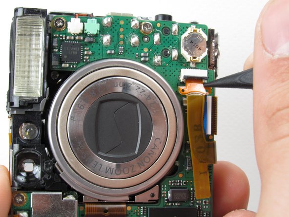
Insert the Spudger into the hole of the ribbon.
Move the Spudger away from the gate to fully remove ribbon.
Be careful not to damage the ribbon.
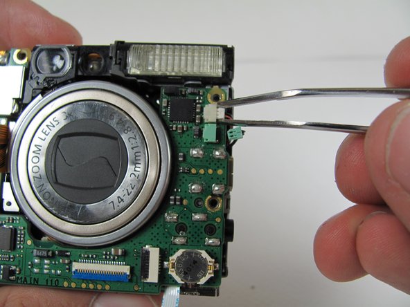
Gently lift the logic board.
Be careful not to pull too hard and damage the white ribbon cable.
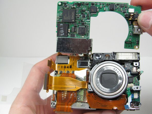
Place the Spudger so that it is between the logic board, the white ribbon cable, and the rest of the camera.
Remove the white ribbon cable by pulling the Spudger away from the camera, keeping it parallel to the logic board.
We're now ready to begin the desoldering process. You'll need a soldering iron, solder, and desoldering wick. You should be able to find these items at a Radio Shack if you don't already have them.
Please do not perform this step if you are not comfortable or have previous experience with soldering. Doing so, could cause severe damage to your camera.
Desolder the two soldered ribbon cables attached to the logic board.
このガイドを埋め込む
サイズを選択し、以下のコードをコピーして、このガイドを小さなウィジェットとしてサイト/フォーラムに埋め込みます。
1つの手順
全ガイド
小サイズ - 600px
中サイズ - 800px
大サイズ - 1200px
プレビュー