はじめに
The LCD screen will be removed and replaced in order to solve an issue with the LCD screen displays operation such as a deep scratch or crack. The LCD is an alternative display that can be used rather than looking through the camera itself.
必要な工具と部品
-
-
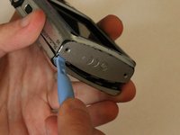
Open the latch at the bottom corner of the device to reveal the battery and SD card housing.
-
There is an orange latch holding the battery in place which must be pushed back in order to free the battery.
-
Once the battery is removed push the SD card and this will activate a spring ejecting the card from the camera.
-
-
-
-
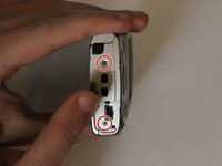
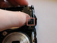
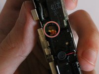
Remove the single philips #00 screw on the button pad which are 2.2mm long. This screw is circled in red in the guide image.
-
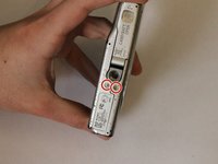
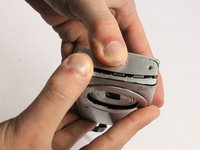
Next, remove the two 2.4mm long screws located in between the LCD screen and the touch pad. These screws will require a Phillips #00 screwdriver.
-
-
-
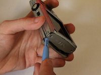
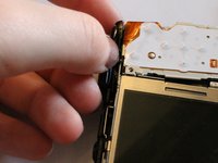
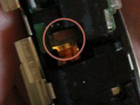
Remove the circuit ribbon connecting the flash to the camera in order to proceed to the next instruction.
-
Carefully pull out the circuit ribbon from the camera which should be the last piece holding the button pad onto the camera.
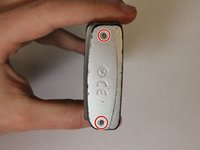
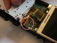
I feel that this guide is missing a step. The third picture shows the plate behind the buttons lifted off, but not how this is done. It appears to be held in place by a screw on the top of the camera that’s beneath the circuitry that I can’t find mentioned in the guide.
That is certainly true as I had to find out after many tries! Jack
Jack Banks - 返信
-
-
-
Lift the tab at the end of the ribbon
-
Disconnect the ribbon from the circuitboard
-


To reassemble your device, follow these instructions in reverse order.
To reassemble your device, follow these instructions in reverse order.
ある他の人がこのガイドを完成しました。
チーム

UMass Dartmouth, Team 3-4, Duarte Spring 2015 UMass Dartmouth, Team 3-4, Duarte Spring 2015人のメンバー
UMASSD-DUARTE-S15S3G4
4 メンバー
12のガイドは作成済み
コメント 1 件
There seams to be a step missing on step 6 . As there is a screw that has to be removed covered to the left of button on top of camera.
Jack Banks - 返信