メインコンテンツにスキップ

このバージョンは誤った内容を含んでいる可能性があります。最新の承認済みスナップショットに切り替えてください。

必要な工具と部品

  1. この手順は未翻訳です。 翻訳を手伝う。

    : 手順 1、 1の画像 1
    • Take the LCD out of its place to expose the Phillips #PH00 screws.

    • Remove the two 2.5 mm Phillips #PH00 black screws on both sides of the LCD screen.

    • Next remove the two 3 mm Phillips #PH00 black screws near both sides of the base where the screen swivels.

  2. この手順は未翻訳です。 翻訳を手伝う。

    : 手順 2、 1の画像 1
    • Using a plastic opening tool, carefully pry off the back cover of the LCD.

  3. この手順は未翻訳です。 翻訳を手伝う。

    : 手順 3、 2の画像 1 : 手順 3、 2の画像 2
    • Remove the 3 mm Phillips #PH00 silver screw on the side of the screen.

    • Turn the screen to remove the second 3 mm Phillips #PH00 silver screw.

  4. この手順は未翻訳です。 翻訳を手伝う。

    : 手順 4、 1の画像 1
    この手順で使用する道具:
    Tweezers
    $4.99
    購入する
    • Using the tweezers, carefully disconnect the rear connector by pulling it away from the screen.

  5. この手順は未翻訳です。 翻訳を手伝う。

    : 手順 5、 2の画像 1 : 手順 5、 2の画像 2
    • Now, four 2.2 mm Phillips #PH00 screws holding a cover around the hinge should be visible.

    • Turn the swivel around to expose the remaining of the aforementioned screws.

    • Then use the PH00 screw driver to remove them.

  6. この手順は未翻訳です。 翻訳を手伝う。

    : 手順 6、 2の画像 1 : 手順 6、 2の画像 2
    • The eye piece will slide right off with a firm push upwards.

    • Remove the 3.4 mm Phillips #PH00 screw using a PH00 screw driver.

    • Remove the two 9.9 mm Phillips #PH00 screws using the PH00 screwdriver.

  7. この手順は未翻訳です。 翻訳を手伝う。

    : 手順 7、 1の画像 1
    • Using the PH00 screwdriver, remove the 3.8 mm Phillips #PH00 screw located on the back of the camera.

  8. この手順は未翻訳です。 翻訳を手伝う。

    : 手順 8、 2の画像 1 : 手順 8、 2の画像 2
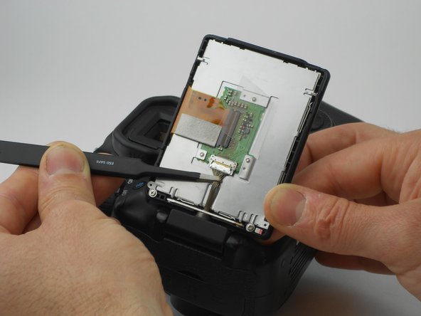
    • Using the plastic opening tool, carefully pull up the rubber grip around the port side of the camera.

    • Remove the four different sized screws located beneath the rubber grip.

    • 6 mm Phillips #PH00 screw.

    • 3.4 mm Phillips #PH00 screw.

    • 3.9 mm Phillips #PH00 screw.

    • 2.2 mm Phillips #PH00 screw.

  9. この手順は未翻訳です。 翻訳を手伝う。

    : 手順 9、 2の画像 1 : 手順 9、 2の画像 2
    • Using the plastic opening tool, carefully pry off the the side cover.

  10. この手順は未翻訳です。 翻訳を手伝う。

    : 手順 10、 1の画像 1
    • Remove two 4.8 mm Phillips #PH00 screws from the memory card side of camera using the PH00 screwdriver.

  11. この手順は未翻訳です。 翻訳を手伝う。

    : 手順 11、 1の画像 1
    • Look at the bottom of the camera so the serial number tag reads up right.

    • Using the PH00 screw driver, remove the top three 3.5 mm Phillips #PH00 screws.

  12. この手順は未翻訳です。 翻訳を手伝う。

    : 手順 12、 1の画像 1
    • Now gently pull the back cover off the camera.

    • Gently pull the orange wire connected to the motherboard of the camera up and off of the motherboard.

ゴール

ある他の人がこのガイドを完成しました。

作成者

5人の作成者と共同で作成されました。

Tyler Vaal

メンバー登録日: 08/30/15

695 ポイント

3のガイドは作成済み

チーム

USF Tampa, Team 16-6, Wollert Fall 2015 USF Tampa, Team 16-6, Wollert Fall 2015人のメンバー

USFT-WOLLERT-F15S16G6

3 メンバー

14のガイドは作成済み

0 件のコメント

コメントを追加

統計データ:

過去 24時間: 0

過去 7 日: 9

過去 30 日: 32

今までの合計 2,380