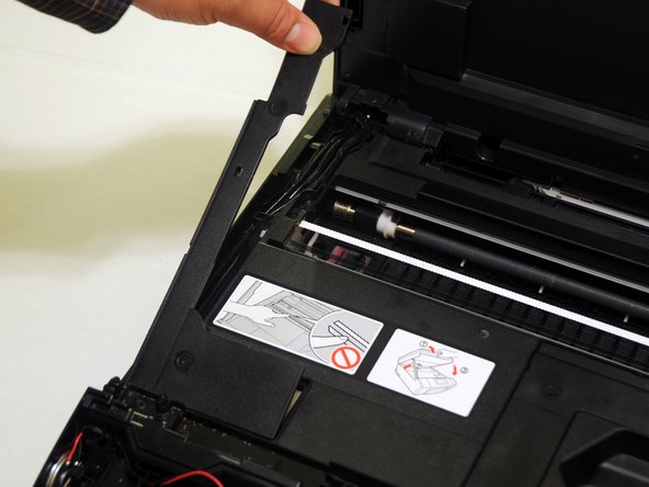
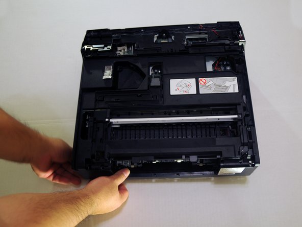
Lift the scanner unit lid.
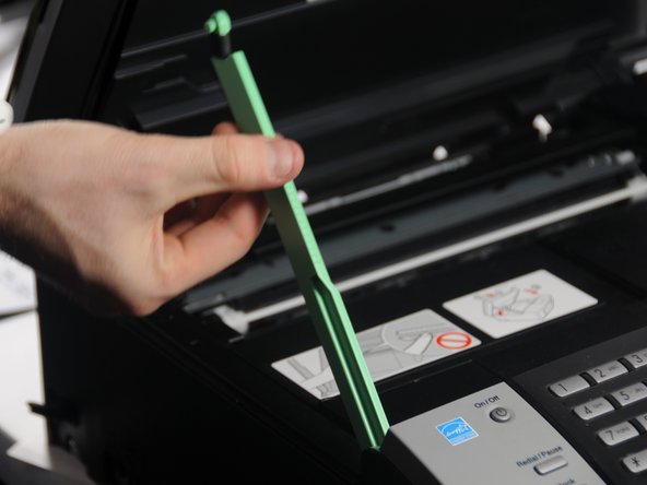
Gently twist the top portion of the arm. The top portion should release from the scanner unit.
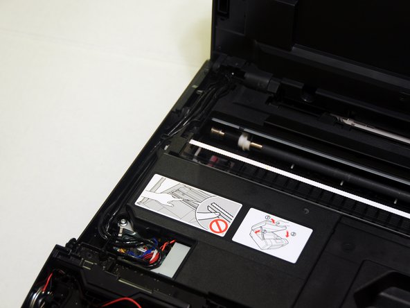
Rotate the arm approximately 45 degrees to remove the bottom portion from the device.
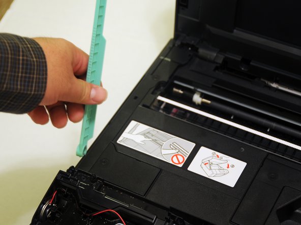
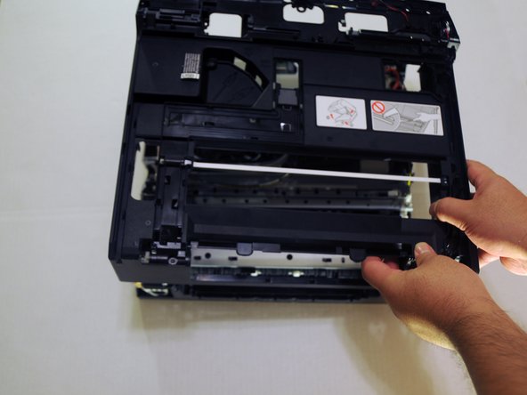
Before removing the unit, apply 2-3 pieces of tape to secure the top and bottom of the unit.
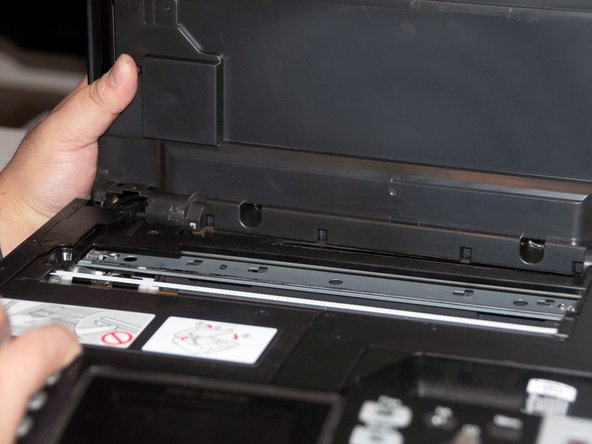
Slide the unit either to the left or right and push it away from the device.
Once one hinge is separated from the device, begin to remove the other hinge.
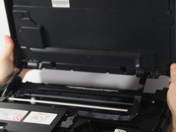
Gently place the unit on the work surface.
Be careful not to pull too hard. The wires connecting the unit to the device must be removed.
From the back of the device, use the exposed portion of the panel and gently begin to remove the panel away from the device.
While it is not necessary to use a prying tool, a thin prying tool can help lift the panels.
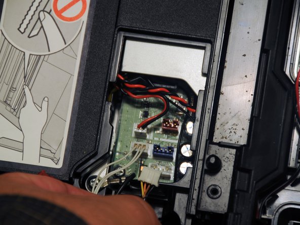
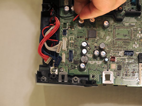
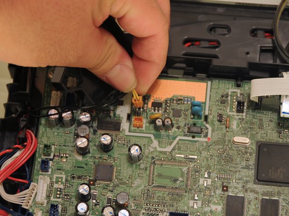
Remove the three power cables that connect the scanner to the motherboard on the left side.
Before removing the cables, create a diagram of their locations. Label the cables with some tape or post-its.
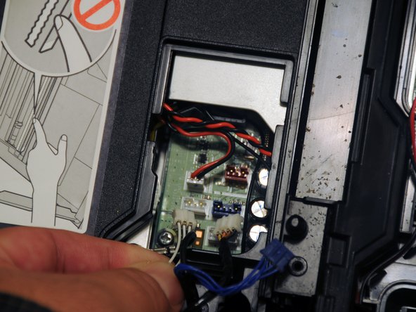
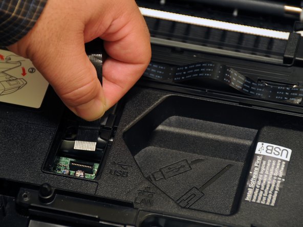
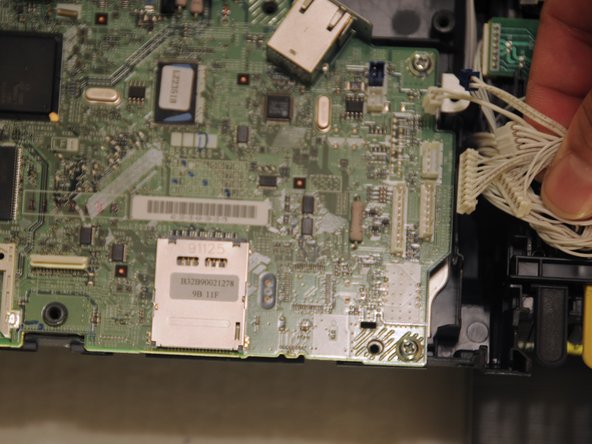
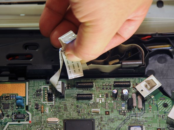
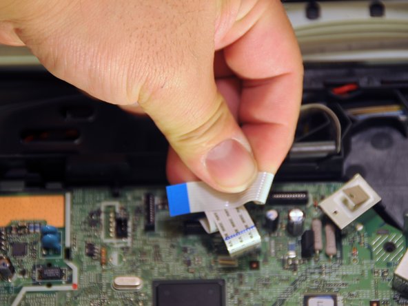
Gently pull the data cable out of the motherboard.
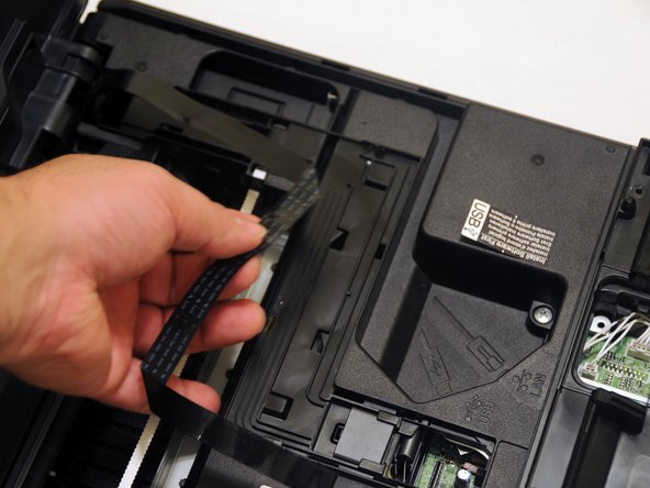
Slide the cable out of the slots to remove it from the device.
Once separated, place the unit and ground screw in a safe area of the workspace until they are needed for re-assembly.
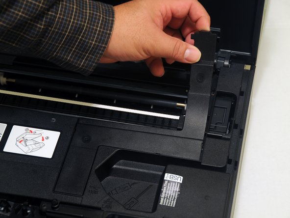
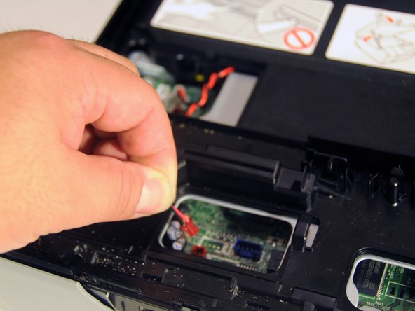
Gently push the upper-left tab of the paper jam clear cover and separate the hinged portion of the cover from the rest of the device.
Once one side of free, slide the other side away from the device.
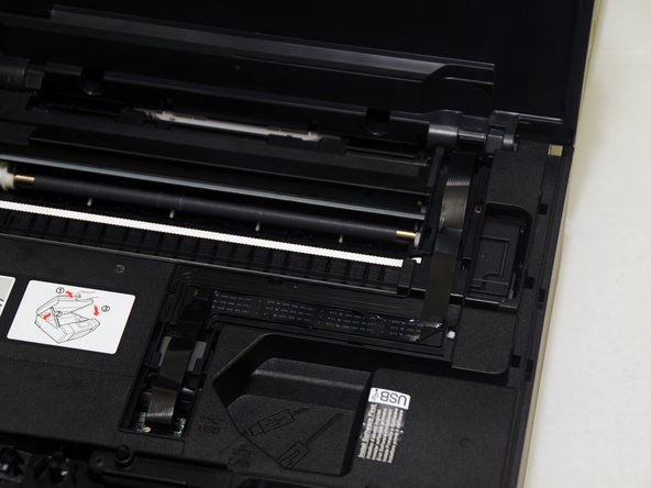
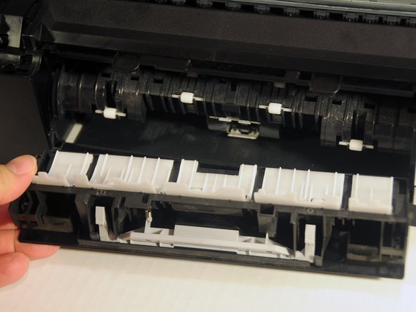
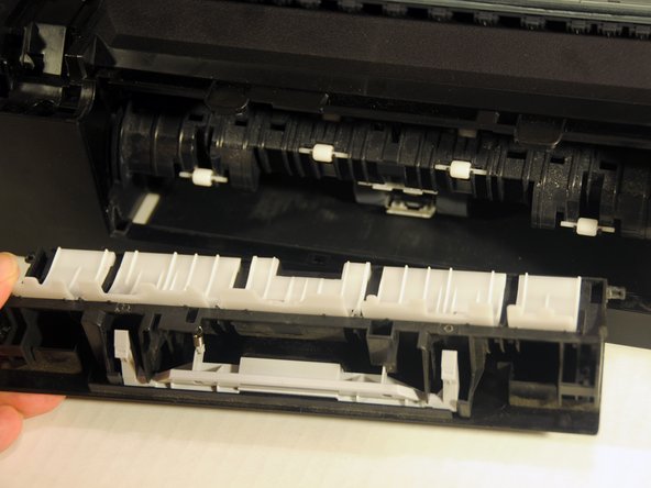
Pull the cover away from the device.
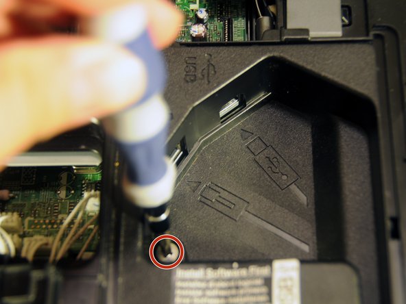
Using a spudger, loosen the two clipped portions of the cover located at the back-center of the device.
Once the clips are free the rest of the cover can be lifted up and away from the device.
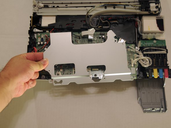
Unscrew the three 8.3mm screws from the motherboard cover.
Lift the motherboard cover away from the device.
Be careful, the motherboard cover may get stuck to the ethernet port. Simply slide the cover until it clears the port.
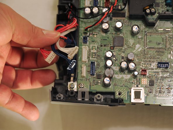
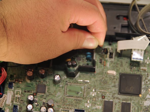
Gently pull the five power cables on the left side, away from the motherboard.
Label the cables with post-its or tape before removal.
Lable the white cable before removal.
Add a label to the port where the white power cable is inserted.
Remove the rear black and white power cables.
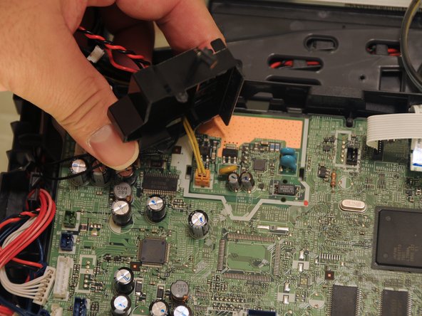
Squeeze the clips of the cover protecting the orange power cable.
Lift the cover away from the motherboard and set it aside.
Gently lift the orange power cable away from the motherboard.
Gently, lift the data cables away from the motherboard.
To avoid any confusion, create a diagram of the location of the data cables and label the them.
Using a screwdriver, remove the four 12.1 mm screws.
Lift the motherboard away from the rest of the device.
このガイドを埋め込む
サイズを選択し、以下のコードをコピーして、このガイドを小さなウィジェットとしてサイト/フォーラムに埋め込みます。
1つの手順
全ガイド
小サイズ - 600px
中サイズ - 800px
大サイズ - 1200px
プレビュー