メインコンテンツにスキップ

Bottom Plate Removal

必要な工具と部品

  1. Bottom Plate Removal, Remove back cover: 手順 1、 1の画像 1
    • Push down on the screw to depress the spring loaded hinge and release the door.

  2. Bottom Plate Removal, Remove bottom cover: 手順 2、 1の画像 1
    • Remove six 5.3 mm #00 screws.

    • Remove one 3.4 mm #00 screw.

    • The short screw has a machine thread and screws into the plate underneath. The rest screw into the plastic body.

  3. Bottom Plate Removal, Remove left front cover: 手順 3、 1の画像 1
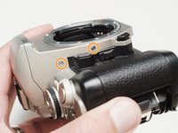
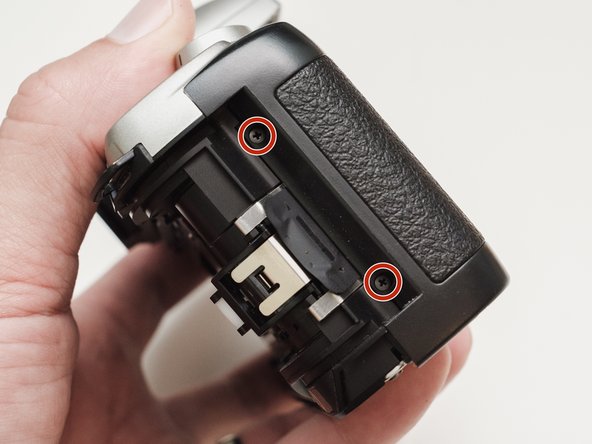
    • Remove three 5.3 mm #00 screws (the bottom-most screw is not always present).

    • Remove one 7.3 mm #00 screw.

    • Remove the remote trigger cover.

  4. Bottom Plate Removal, Remove front cover: 手順 4、 2の画像 1 Bottom Plate Removal, Remove front cover: 手順 4、 2の画像 2
    • Remove one 3.4 mm #00 screw.

    • Remove two 5.3 mm #00 screw.

    • Gently lift up on the flash housing to help remove the cover if necessary.

  5. Bottom Plate Removal, Remove right front cover: 手順 5、 1の画像 1
    • Remove two 3.9 mm #00 screws.

  6. Bottom Plate Removal, Remove eye cup: 手順 6、 1の画像 1
    • Slide the eye cup up and off to access the screws underneath.

  7. Bottom Plate Removal, Unscrew top cover: 手順 7、 3の画像 1 Bottom Plate Removal, Unscrew top cover: 手順 7、 3の画像 2 Bottom Plate Removal, Unscrew top cover: 手順 7、 3の画像 3
    • Remove two 5.3 mm #00 screws by the eyepiece.

    • Remove one 6.8 mm #00 screw in the battery compartment.

    • Remove one 7.0 mm #00 screw near the take up spool.

  8. Bottom Plate Removal, Lift top cover: 手順 8、 1の画像 1
    • Lift the cover so it is just free of the body. It is still attached by several wires.

  9. Bottom Plate Removal, Prepare bottom plate: 手順 9、 2の画像 1 Bottom Plate Removal, Prepare bottom plate: 手順 9、 2の画像 2
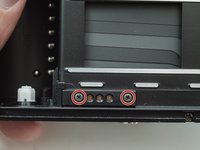
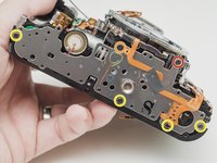
    • Remove two 3.4 mm #00 screws. Remove the plate holding the contacts in place.

    • Peel tape from the plate. Leave the tape attached to the flex circuit.

    • Remove the flex circuits from their retaining studs.

  10. Bottom Plate Removal, Remove bottom plate: 手順 10、 2の画像 1 Bottom Plate Removal, Remove bottom plate: 手順 10、 2の画像 2
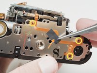
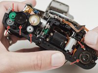
    • Remove one 3.3 mm #0 countersunk screw.

    • Remove one 3.9 mm #0 shoulder screw.

    • Remove four 3.3 mm #00 screws.

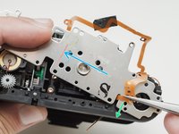
    • Pull a little slack through the housing on this flex cable.

    • Pop the plate off its posts, rotate slightly clockwise and pull gently through the loosened flex cable.

    • To the camera tech that left me a happy little note...I see you.

  11. Bottom Plate Removal, Remove loose parts: 手順 11、 2の画像 1 Bottom Plate Removal, Remove loose parts: 手順 11、 2の画像 2
    • It's best to remove these parts now so they don't fall out later on in the repair.

終わりに

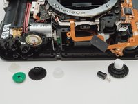
To reassemble your device, follow these instructions in reverse order.

作成者

1人の作成者と共同作成されました。

Sam Gustafson

メンバー登録日: 09/01/22

3,233 ポイント

13のガイドは作成済み

0 件のコメント

コメントを追加

統計データ:

過去 24時間: 0

過去 7 日: 3

過去 30 日: 14

今までの合計 199