メインコンテンツにスキップ

このバージョンは誤った内容を含んでいる可能性があります。最新の承認済みスナップショットに切り替えてください。

必要な工具と部品

  1. この手順は未翻訳です。 翻訳を手伝う。

    : 手順 1、 1の画像 1
    • Remove the six # 1 Phillips head screws from the bottom panel.

  2. この手順は未翻訳です。 翻訳を手伝う。

    : 手順 2、 1の画像 1
    • After removing the bottom plate, you will have visibility of the logic board. Using a plastic opening tool, lift the small black latch holding the ribbon cable. Slide the ribbon cable loose from the logic board.

  3. この手順は未翻訳です。 翻訳を手伝う。

    : 手順 3、 1の画像 1
    • Next, using pointed nose tweezers, remove the 4-wire white connector from the logic board by wiggle back and forth while lifting until the connector is disconnected from the board.

    • Metal pointed nose tweezers may cause damage if used improperly.

  4. この手順は未翻訳です。 翻訳を手伝う。

    : 手順 4、 1の画像 1
    • Remove the remaining 8mm length # 2 Phillips head screws holding the motherboard in place.

  5. この手順は未翻訳です。 翻訳を手伝う。

    : 手順 5、 2の画像 1 : 手順 5、 2の画像 2
    この手順で使用する道具:
    Desoldering Pump
    $3.99
    購入する
    • Record the order of the 6 wires soldered to the board.

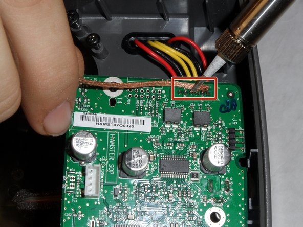
    • Using a hot soldering iron and either a solder sucker or de-soldering wick, remove the solder from the 6 wires highlighted on the photo in red.

    • Soldering iron may cause damage to the device if used improperly.

  6. この手順は未翻訳です。 翻訳を手伝う。

    : 手順 6、 1の画像 1
    • Replace old logic board with the new logic board. Place the wires into the solder holes and solder in place. Reassemble the SoundDock.

    • Make sure the wires are in the correct order using the recorded pattern from the wire removal step 3.

ゴール

4 の人々がこのガイドを完成させました。

作成者

4人の作成者と共同で作成されました。

redacted

メンバー登録日: 09/29/15

288 ポイント

2のガイドは作成済み

チーム

IUPUI, Team 1-4, Hagerty Fall 2015 IUPUI, Team 1-4, Hagerty Fall 2015人のメンバー

IUPUI-HAGERTY-F15S1G4

5 メンバー

3のガイドは作成済み

コメント 1 件

Hi, one question, where can i buy the replacement logic board?

Nahir Romero - 返信

コメントを追加

統計データ:

過去 24時間: 0

過去 7 日: 3

過去 30 日: 13

今までの合計 2,159