はじめに
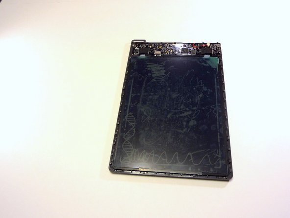
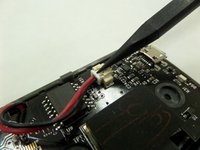
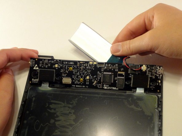
This guide shows how to safely access the device's internal components, including circuit board, battery, and internal antenna.
必要な工具と部品
-
-
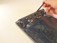
On the back of the device, remove the four 3/8" Torx head screws using the T-6 Torx bit.
-
-


To reassemble your device, follow these instructions in reverse order.
2 の人々がこのガイドを完成させました。
チーム

CSU Fullerton, Team 2-6, Bruce Fall 2014 CSU Fullerton, Team 2-6, Bruce Fall 2014人のメンバー
CSUF-BRUCE-F14S2G6
4 メンバー
6のガイドは作成済み
3件のガイドコメント
I pulled mine, 7.4v 830ma, IIRC correctly. I found a similar RC battery, 800ma 7.4v, and bought it. But it is too thick for the casing. Unfortunately, I accidentally dropped the RIP while the front casing was off. This caused one of the linear power tabs connected to the lcd to start separating. So, if I can get it to work again, the upper right quadrant’s upper quadrant is ruined. Up until now, ended up using the RIP by taping an external battery to ($10 Walmart rechargable pack) and power the RIP with a micro usb cable. The only remaining issue, is how to repair the lcd’s damaged connector to allow it to work again. And, also, whether I can download the data to my PC using a full duplex usb communications/power cable.
Feb 14, 2022
Update on the RIP, worked fine with the external battery. There is no way to repair the damaged corner of the LCD screen. But most of the damaged area is hidden by the frame. Today (7/7/22), I plugged in the microUSB power cord to recharge the battery. The usb port has enough space leeway around the connector to fish the two microwires from the internal mobo battery connector to the outside of the shell to the external battery. I don't have much finesse in jerry-rigging things. Duct tape, etc. I didn't want to drill additional holes in the case. Anyway, one of the microwires had worn against the usb connector's sharp edge and shorted. It took out a smd resistor that was all black, no code. Apparently, this is a kind of jumper. At the moment, the RIP powers up, but its status led just blinks green. After I am certain of the smd resistor Just being a 0 ohm resistor/jumper, I will attempt to solder a replacement into place. Hopefully, that will ensure operation, again. Hafta drill a hole for the wires.