メインコンテンツにスキップ

Black and Decker DCM100R Control Panel Circuit Board Replacement

必要な工具と部品

  1. Black and Decker DCM100R Control Panel Circuit Board Replacement, Heating Element: 手順 1、 2の画像 1 Black and Decker DCM100R Control Panel Circuit Board Replacement, Heating Element: 手順 1、 2の画像 2
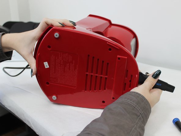
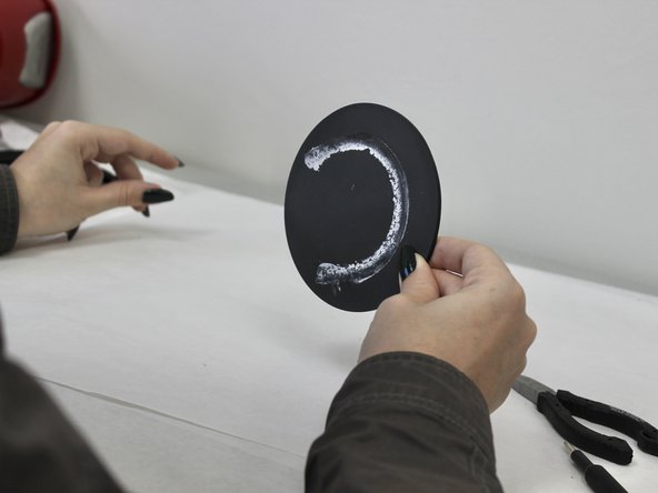
    • Turn the coffee maker on its side.

    • Remove the four 6 mm Phillips #2 that secure the baseplate.

  2. Black and Decker DCM100R Control Panel Circuit Board Replacement: 手順 2、 3の画像 1 Black and Decker DCM100R Control Panel Circuit Board Replacement: 手順 2、 3の画像 2 Black and Decker DCM100R Control Panel Circuit Board Replacement: 手順 2、 3の画像 3
    • Insert the jimmy at the back of the panel and slide it around to the front.

  3. Black and Decker DCM100R Control Panel Circuit Board Replacement: 手順 3、 3の画像 1 Black and Decker DCM100R Control Panel Circuit Board Replacement: 手順 3、 3の画像 2 Black and Decker DCM100R Control Panel Circuit Board Replacement: 手順 3、 3の画像 3
    • Apply pressure to the backside of the panel until it releases.

    • Remove the plate.

  4. Black and Decker DCM100R Control Panel Circuit Board Replacement: 手順 4、 2の画像 1 Black and Decker DCM100R Control Panel Circuit Board Replacement: 手順 4、 2の画像 2
    • Remove the two 10 mm Phillips #2 screws securing the metal support brace.

    • Remove the brace and set aside.

  5. Black and Decker DCM100R Control Panel Circuit Board Replacement: 手順 5、 2の画像 1 Black and Decker DCM100R Control Panel Circuit Board Replacement: 手順 5、 2の画像 2
    この手順で使用する道具:
    Tweezers
    $4.99
    購入する
    • Pull back the tubing and wiring to reveal the hot plate.

    • To hold these out of your way, you can use the Nylon Tipped Tweezers to pin them back to the back panel.

  6. Black and Decker DCM100R Control Panel Circuit Board Replacement: 手順 6、 2の画像 1 Black and Decker DCM100R Control Panel Circuit Board Replacement: 手順 6、 2の画像 2
    • Use a Phillips #2 screwdriver to remove the five 8 mm screws that secure the mounting bracket and hot plate.

  7. Black and Decker DCM100R Control Panel Circuit Board Replacement: 手順 7、 2の画像 1 Black and Decker DCM100R Control Panel Circuit Board Replacement: 手順 7、 2の画像 2
    • Use a pair of pliers to gently pull the mounting bracket out of place.

  8. Black and Decker DCM100R Control Panel Circuit Board Replacement: 手順 8、 3の画像 1 Black and Decker DCM100R Control Panel Circuit Board Replacement: 手順 8、 3の画像 2 Black and Decker DCM100R Control Panel Circuit Board Replacement: 手順 8、 3の画像 3
    • Remove the hot plate from the mounting bracket.

    • Remove the O-ring from the hot plate.

  9. Black and Decker DCM100R Control Panel Circuit Board Replacement, Control Panel Circuit Board: 手順 9、 2の画像 1 Black and Decker DCM100R Control Panel Circuit Board Replacement, Control Panel Circuit Board: 手順 9、 2の画像 2
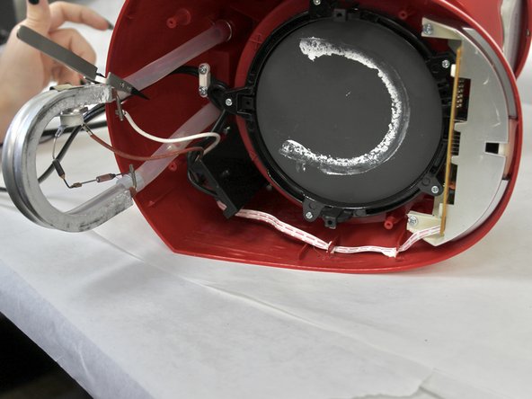
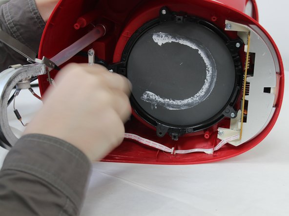
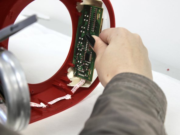
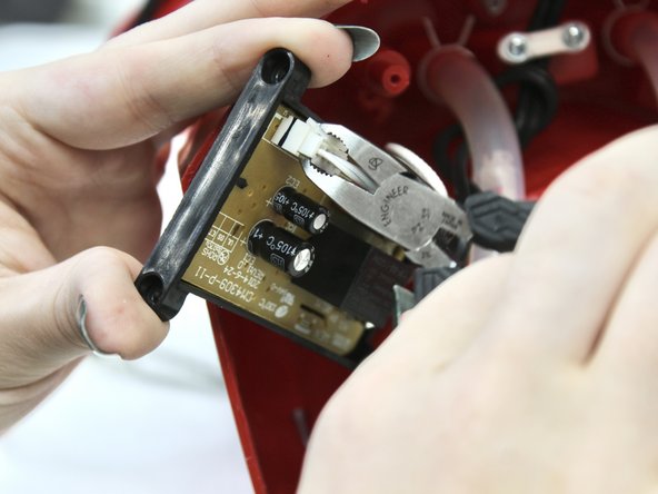
    • Remove the two 6 mm Phillips #2 screws that secure the circuit board.

  10. Black and Decker DCM100R Control Panel Circuit Board Replacement: 手順 10、 2の画像 1 Black and Decker DCM100R Control Panel Circuit Board Replacement: 手順 10、 2の画像 2
    • Pull the circuit board out and over the hooks.

  11. Black and Decker DCM100R Control Panel Circuit Board Replacement: 手順 11、 2の画像 1 Black and Decker DCM100R Control Panel Circuit Board Replacement: 手順 11、 2の画像 2
    • Using the jimmy, pry the circuit board out.

  12. Black and Decker DCM100R Control Panel Circuit Board Replacement: 手順 12、 2の画像 1 Black and Decker DCM100R Control Panel Circuit Board Replacement: 手順 12、 2の画像 2
    • Remove the two 8 mm Phillips #2 screws that hold the main circuit board.

  13. Black and Decker DCM100R Control Panel Circuit Board Replacement: 手順 13、 3の画像 1 Black and Decker DCM100R Control Panel Circuit Board Replacement: 手順 13、 3の画像 2 Black and Decker DCM100R Control Panel Circuit Board Replacement: 手順 13、 3の画像 3
    • Pull out the circuit board and disconnect the white plug.

  14. Black and Decker DCM100R Control Panel Circuit Board Replacement: 手順 14、 3の画像 1 Black and Decker DCM100R Control Panel Circuit Board Replacement: 手順 14、 3の画像 2 Black and Decker DCM100R Control Panel Circuit Board Replacement: 手順 14、 3の画像 3
    • Dislodge the ribbon cable.

終わりに

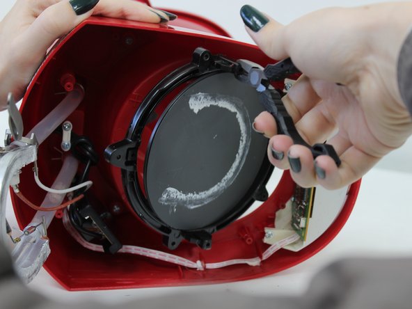
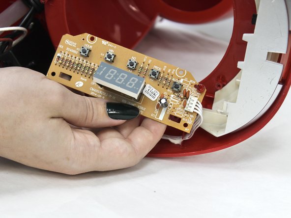
To reassemble your device, follow these instructions in reverse order.

作成者

3人の作成者と共同で作成されました。

Rory O'Neal

メンバー登録日: 09/13/23

133 ポイント

1ガイドが承認済み

チーム

University of North Texas, Team 6-6, Kilpatrick Fall 2023 University of North Texas, Team 6-6, Kilpatrick Fall 2023人のメンバー

UNT-KILPATRICK-F23S6G6

4 メンバー

5のガイドは作成済み

0 件のコメント

コメントを追加

統計データ:

過去 24時間: 0

過去 7 日: 0

過去 30 日: 6

今までの合計 124