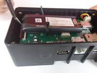
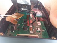
メインコンテンツにスキップ

BRCK v1 Modem Ribbon Connector Replacement

必要な工具と部品

  1. BRCK v1 Modem Ribbon Connector Replacement, Top Cover: 手順 1、 1の画像 1
    • Place the face of the device showing BRCK face up.

  2. BRCK v1 Modem Ribbon Connector Replacement: 手順 2、 1の画像 1
    • Remove the four screws(4mm hex head) on the corners of the device with a Hex 2.0 Screwdriver.

  3. BRCK v1 Modem Ribbon Connector Replacement: 手順 3、 1の画像 1
    • Remove the top cover.

  4. BRCK v1 Modem Ribbon Connector Replacement, Modem: 手順 4、 1の画像 1
    • Cut the black zip tie holding the modem down.

    • Caution By cutting the zip tie, you void any manufacturer warranty you may have on the device.

  5. BRCK v1 Modem Ribbon Connector Replacement: 手順 5、 1の画像 1
    • Remove the connection located on the edge of the modem.

  6. BRCK v1 Modem Ribbon Connector Replacement: 手順 6、 2の画像 1 BRCK v1 Modem Ribbon Connector Replacement: 手順 6、 2の画像 2
    • Slightly lift the modem to reveal the brown ribbon connector and metal connection plate, located on the bottom of the modem.

  7. BRCK v1 Modem Ribbon Connector Replacement: 手順 7、 3の画像 1 BRCK v1 Modem Ribbon Connector Replacement: 手順 7、 3の画像 2 BRCK v1 Modem Ribbon Connector Replacement: 手順 7、 3の画像 3
    • Using your tweezers, gently push on the metal plate and slide it down toward the base of the modem to release the locking mechanism.

    • Lower the plate and gently pull the ribbon out of the face plate.

    • Caution Be extremely gentle while preforming this step. The ribbon is brittle and prone to breaking if bent too much. Make sure you go slowly so that you do not damage the device.

  8. BRCK v1 Modem Ribbon Connector Replacement: 手順 8、 2の画像 1 BRCK v1 Modem Ribbon Connector Replacement: 手順 8、 2の画像 2
    • Remove the modem from the device.

  9. BRCK v1 Modem Ribbon Connector Replacement, Modem Ribbon Connector: 手順 9、 3の画像 1 BRCK v1 Modem Ribbon Connector Replacement, Modem Ribbon Connector: 手順 9、 3の画像 2 BRCK v1 Modem Ribbon Connector Replacement, Modem Ribbon Connector: 手順 9、 3の画像 3
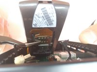
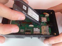
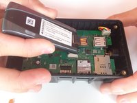
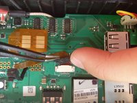
    • Using your fingers, apply equal force to each side of the black tab to loosen the connection.

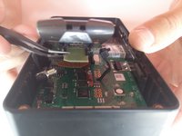
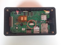
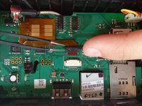
    • Slide the ribbon out from under the black tab.

終わりに

To reassemble your device, follow these instructions in reverse order.

作成者

3人の作成者と共同で作成されました。

Jeret Buerger

メンバー登録日: 04/01/15

501 ポイント

5のガイドは作成済み

チーム

Cal Poly, Team 12-3, Lancaster Spring 2015 Cal Poly, Team 12-3, Lancaster Spring 2015人のメンバー

CPSU-LANCASTER-S15S12G3

3 メンバー

14のガイドは作成済み

0 件のコメント

コメントを追加

統計データ:

過去 24時間: 0

過去 7 日: 4

過去 30 日: 4

今までの合計 159