メインコンテンツにスキップ

Autosampler Node Wiring (For Old Version)

必要な工具と部品

  1. Autosampler Node Wiring  (For Old Version), Disconnect the batteries completely: 手順 1、 3の画像 1 Autosampler Node Wiring  (For Old Version), Disconnect the batteries completely: 手順 1、 3の画像 2 Autosampler Node Wiring  (For Old Version), Disconnect the batteries completely: 手順 1、 3の画像 3
    • 1. Disconnect the plug to the solar panel.

    • Then, grabbing the green connector, pull the battery connector from the solar charge controller (blue arrow).

    • 2. Disconnect the plugs for the autosampler battery.

    • 3. Disconnect the connector that plugs into the battery port of the sampler.

    • If disconnect battery before solar panel, this can damage the solar charger!

  2. Autosampler Node Wiring  (For Old Version), Remove old wires: 手順 2、 2の画像 1 Autosampler Node Wiring  (For Old Version), Remove old wires: 手順 2、 2の画像 2
    • 4. Unscrew conduit and release to open up more space to work with.

    • 5. Unscrew existing wires using 260 / 1.5 x 40 flathead screwdriver.

  3. Autosampler Node Wiring  (For Old Version), Run wires through enclosure: 手順 3、 1の画像 1
    • 6. Pull the autosampler and battery wires through the conduit. Reattach the conduit to provide strain relief and prevent wires from being dragged down.

  4. Autosampler Node Wiring  (For Old Version), Rewire the autosampler connections: 手順 4、 3の画像 1 Autosampler Node Wiring  (For Old Version), Rewire the autosampler connections: 手順 4、 3の画像 2 Autosampler Node Wiring  (For Old Version), Rewire the autosampler connections: 手順 4、 3の画像 3
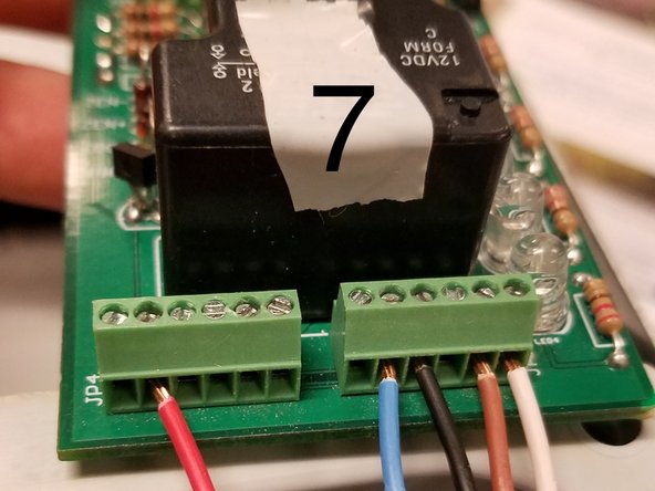
    • 7. Insert the wires and screw down using 260 / 1.5 x 40 flathead screwdriver until tight.

    • We do not use the green wire.

    • Hand tight is just right. Be careful not to over-tighten and crush the wire ferrules

    • 8. The battery connectors go in the fifth and sixth positions from the left.

    • If the battery connectors do not have the white caps, they will be only one red and one black wire. To make it easier to connect to the board, trim half of the copper wires off of each wire. and twist the reaming threads together. The red wire goes in the place where the red/white cap goes and the black wire goes where the black/green wire goes.

  5. Autosampler Node Wiring  (For Old Version), Connect the relay board: 手順 5、 1の画像 1
    • 9. Plug in the pluggable header into the board.

  6. Autosampler Node Wiring  (For Old Version), Tidy up the enclosure: 手順 6、 3の画像 1 Autosampler Node Wiring  (For Old Version), Tidy up the enclosure: 手順 6、 3の画像 2 Autosampler Node Wiring  (For Old Version), Tidy up the enclosure: 手順 6、 3の画像 3
    • 10. Using velcro, re-secure the relay board to the side of the enclosure.

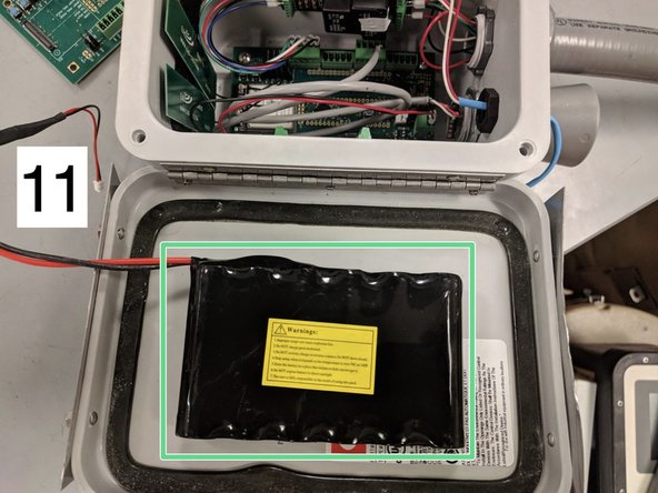
    • 11. Using velcro, attach the lithium ion battery to the inside of the enclosure door.

    • Be sure to clean the surfaces beforehand.

    • Be sure the soft side is attached to the enclosure.

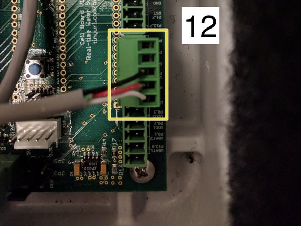
    • 12. In case the wiring of an ultrasonic sensor comes loose, here is the wiring.

  7. Autosampler Node Wiring  (For Old Version), Reconnect wires to the autosampler.: 手順 7、 2の画像 1 Autosampler Node Wiring  (For Old Version), Reconnect wires to the autosampler.: 手順 7、 2の画像 2
    • 13. Reconnect the 6-pin autosampler connector.

    • 14. Reconnect the 2-pin autosampler battery to the autosampler.

  8. Autosampler Node Wiring  (For Old Version), Reconnect the batteries: 手順 8、 3の画像 1 Autosampler Node Wiring  (For Old Version), Reconnect the batteries: 手順 8、 3の画像 2 Autosampler Node Wiring  (For Old Version), Reconnect the batteries: 手順 8、 3の画像 3
    • 15. Reconnect the grey autosampler connector from the autosampler to the node.

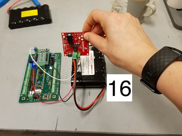
    • 16. Reconnect lithium ion battery in the node.

    • 17. Plug in the solar panel into the solar charger last.

終わりに

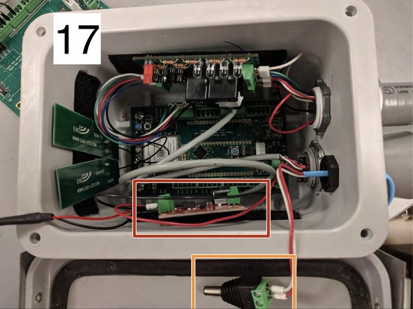
Now we can close and lock up the enclosure. The node is ready to test and confirm everything is working,

2 の人々がこのガイドを完成させました。

作成者

4人の作成者と共同で作成されました。

Brandon Wong

メンバー登録日: 01/16/18

502 ポイント

2のガイドは作成済み

0 件のコメント

コメントを追加

統計データ:

過去 24時間: 1

過去 7 日: 4

過去 30 日: 13

今までの合計 535