はじめに
My USB-C charging port stopped charging reliably and when plugged in to known good chargers and cables, would only charge if the cable was in exactly the right position and did not move.
必要な工具と部品
-
-
Power off the phone.
-
Using a removal tool or a paper clip, open the SIM card tray and fully remove it from the phone.
-
-
-
Using an iOpener or heat gun, warm the adhesive around the edges of the back cover to soften it.
-
Once softened, run an opening pick or guitar pick around the edge of the phone to separate the back cover from the phone.
-
If you are unable to wedge the pick underneath the cover, you could try to shave down the pick to make it thinner or use a sharp instrument to get it started. Once you pry it open enough to get a pick underneath, use that exclusively.
-
PROTIP: If you need to use a sharp instrument, there is much less chance of damaging delicate internals by starting at the bottom of the phone because the speaker array is fully encased in plastic.
-
-
-
Use a 000 philips bit to remove the nine highlighted screws. The screw highlighted in yellow has a decal on top of it which you can easily remove with a sharp instrument.
-
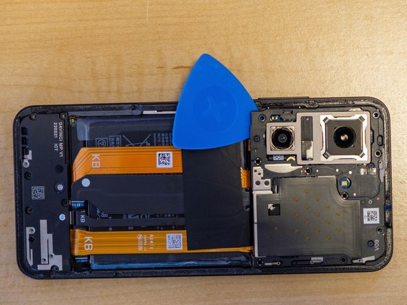
Pop off the plastic cover using a spudger, opening pick, or guitar pick.
-
PROTIP: Start near the battery to avoid damage to the flat cables or the camera modules.
-
-
-
-
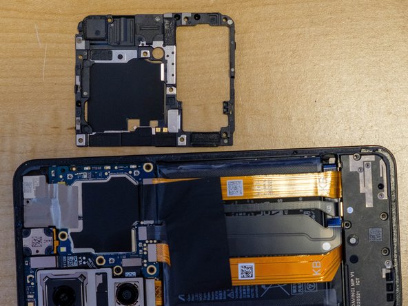
Using a 000 philips bit, remove the six highlighted screws.
-
Once again, there is a sticker covering the screw highlighted in yellow, which can be removed easily with a sharp instrument.
-
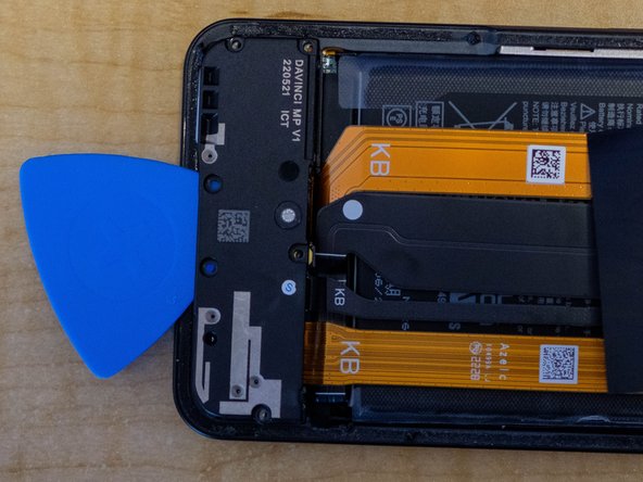
Pop out the speaker using your finger, an opening pick, or guitar pick.
-
-
-
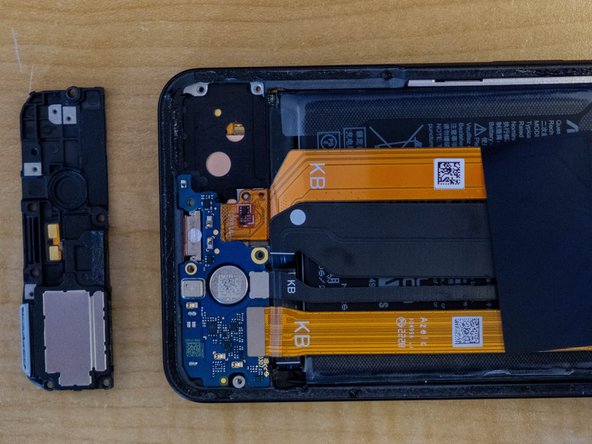
Using a spudger, opening pick or guitar pick, gently pop out the circuit board. This circuit board also holds the SIM card reader.
-
You do not have to disconnect the two flat cables from the main board, but DO NOT bend or fold them if you leave them connected.
-
-
-
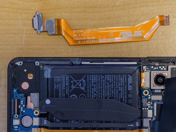
Using a spudger, pop off the old USB-C connector's connection to the main board, on the right in this photo.
-
With a firm grasp on the flat cable, pull back on the "KB" side to release the adhesive holding it to back of the phone case. This requires some force, so be careful.
-
The USB-C port will pop out from the case with the flat cable and can be removed.
-
-
-
Remove the blue plastic covering the adhesive on the new cable.
-
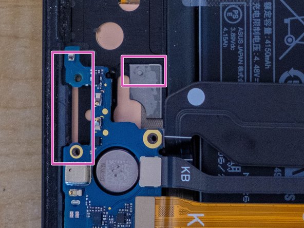
Align the cable so the side marked "KB" is up and toward the bottom of the phone.
-
Insert the new port where the old one was. Note the red gasket seals the connection, so it will be tight. The cable is keyed to the gray plastic peg highlighted in the second photo.
-
Make sure the screw holes in the new port align perfectly with the circuit board.
-
Once satisfied, press the cable down over the plastic peg which will attach the adhesive.
-
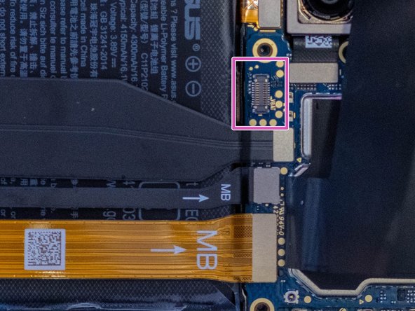
Reconnect the "MB" side of the cable to the highlighted port on the main board. It will just pop into place when properly aligned.
-


To reassemble your device, follow these instructions in reverse order.
To reassemble your device, follow these instructions in reverse order.