メインコンテンツにスキップ

Asus Q304UA Motherboard Replacement

必要な工具と部品

  1. Asus Q304UA Motherboard Replacement, Remove the bottom cover: 手順 1、 1の画像 1
    この手順で使用する道具:
    Magnetic Project Mat
    $19.95
    購入する
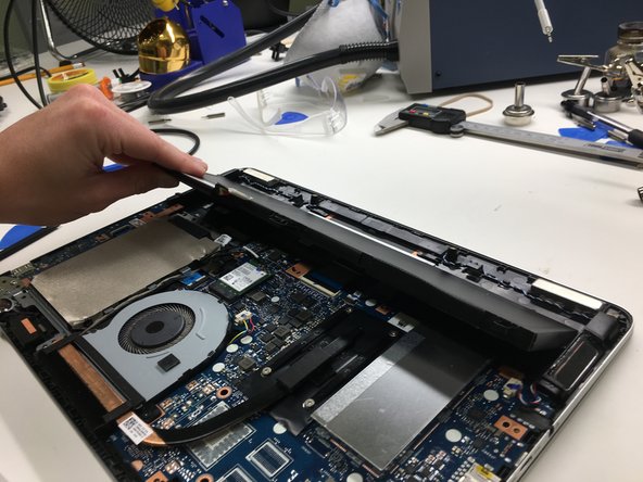
    • Remove ten Phillips #0 screws that secure the plastic bottom cover to the chassis.

    • Six 9.6 mm screws

    • Four 4.6 mm screws

    • Throughout this guide, keep careful track of your screws so that each one goes back where it came from during reassembly. Installing a screw in the wrong place can cause permanent damage.

  2. Asus Q304UA Motherboard Replacement: 手順 2、 3の画像 1 Asus Q304UA Motherboard Replacement: 手順 2、 3の画像 2 Asus Q304UA Motherboard Replacement: 手順 2、 3の画像 3
    • Use a plastic pry tool to get in-between the bottom cover and the lower case assembly.

    • Be careful not separate the cover too violently or you will risk breaking the plastic clips that are on the bottom cover.

  3. Asus Q304UA Motherboard Replacement, Disconnect the battery: 手順 3、 3の画像 1 Asus Q304UA Motherboard Replacement, Disconnect the battery: 手順 3、 3の画像 2 Asus Q304UA Motherboard Replacement, Disconnect the battery: 手順 3、 3の画像 3
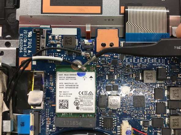
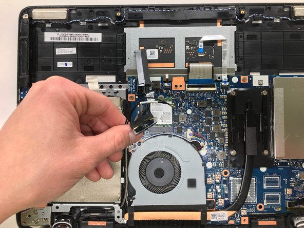
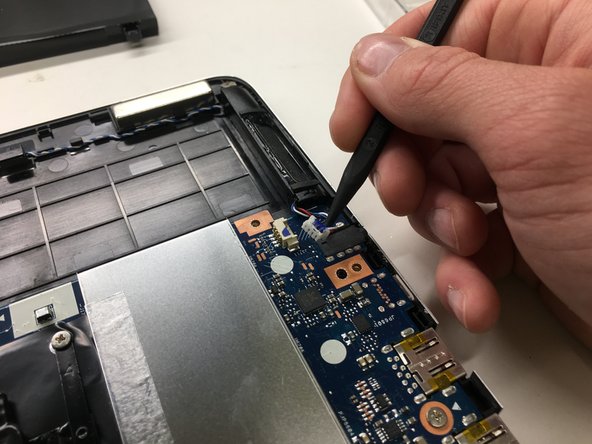
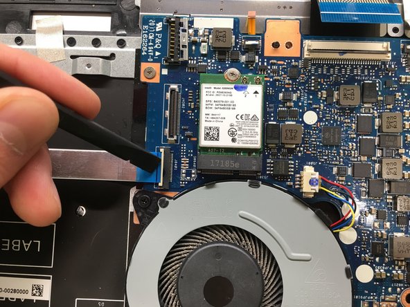
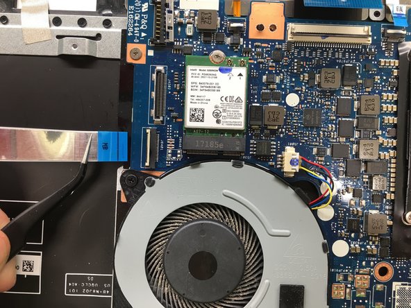
    • Push metal bracket away from battery connector.

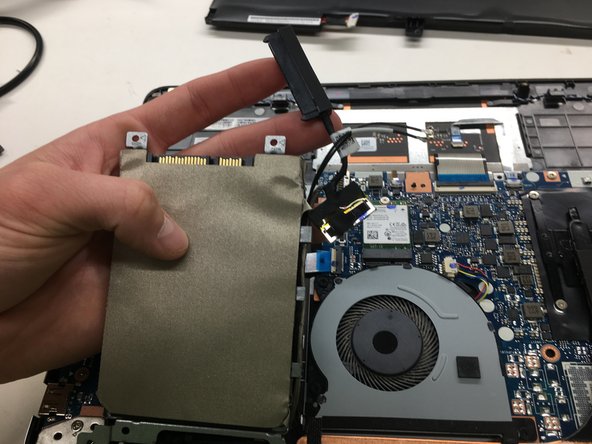
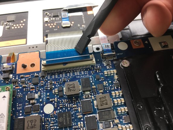
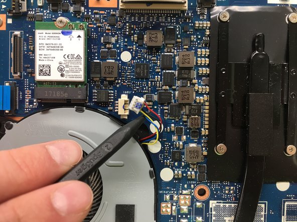
    • Use a spudger to push the battery connection straight up.

    • If you pry too hard, or attempt to disconnect the battery with the metal bracket still in place, you risk pulling the connector off of the motherboard.

    • Make sure the computer is powered off before removing the battery.

  4. Asus Q304UA Motherboard Replacement, Remove the battery: 手順 4、 1の画像 1
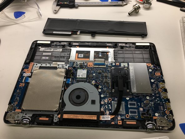
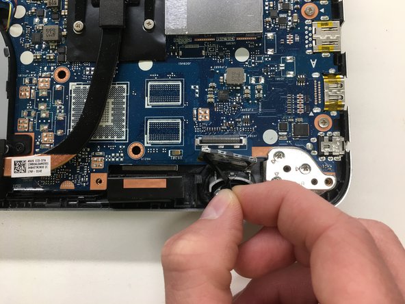
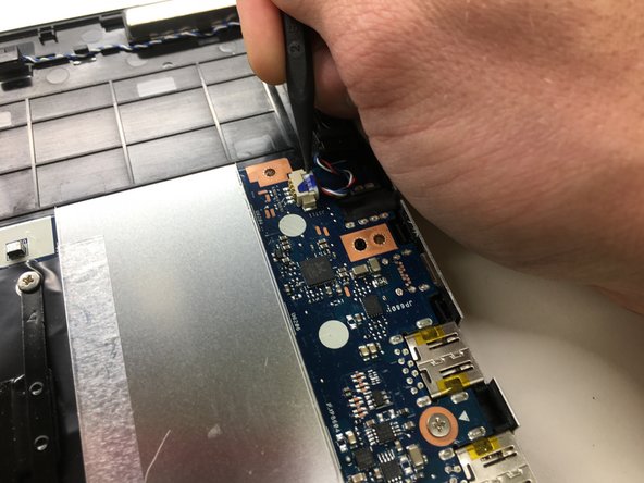
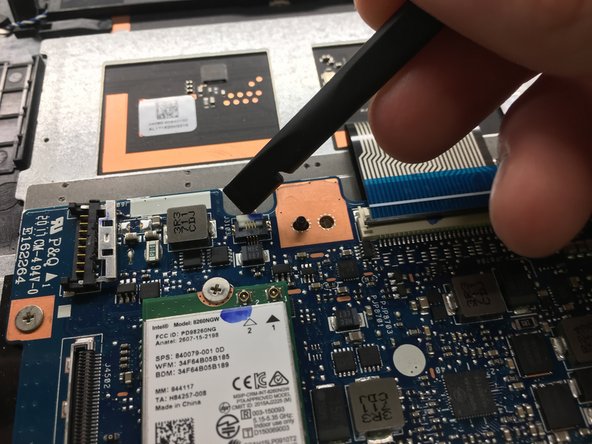
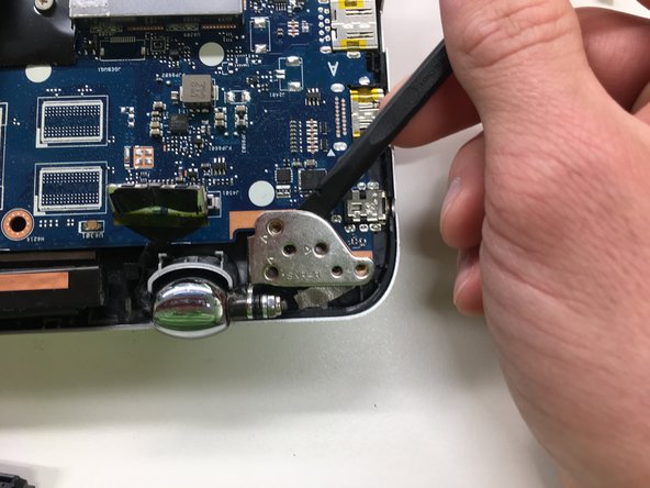
    • Remove the Phillips #0 screws that secure the battery to the lower case assembly

    • Three 4.7 mm screws.

  5. Asus Q304UA Motherboard Replacement: 手順 5、 3の画像 1 Asus Q304UA Motherboard Replacement: 手順 5、 3の画像 2 Asus Q304UA Motherboard Replacement: 手順 5、 3の画像 3
    • Tilt battery up from the side closest to the motherboard

    • Pull the battery out of the chassis away from the two plastic retainers near the front of the laptop.

  6. Asus Q304UA Motherboard Replacement, Disconnect RF cables: 手順 6、 3の画像 1 Asus Q304UA Motherboard Replacement, Disconnect RF cables: 手順 6、 3の画像 2 Asus Q304UA Motherboard Replacement, Disconnect RF cables: 手順 6、 3の画像 3
    • Disconnect the Wifi/Bluetooth RF cables from the wireless card.

    • Pull the RF cables by the metal connector, not by the rubber shielding. This avoids damaging the connector and the cable.

  7. Asus Q304UA Motherboard Replacement, Remove the drive: 手順 7、 2の画像 1 Asus Q304UA Motherboard Replacement, Remove the drive: 手順 7、 2の画像 2
    • Pull straight up to disconnect the SATA combo cable from the motherboard.

  8. Asus Q304UA Motherboard Replacement: 手順 8、 1の画像 1
    • Remove three Phillips #0 that secure the hard drive bracket to the chassis, of the following lengths:

    • Two 2.3 mm screws

    • One 5.6 mm screw

  9. Asus Q304UA Motherboard Replacement: 手順 9、 3の画像 1 Asus Q304UA Motherboard Replacement: 手順 9、 3の画像 2 Asus Q304UA Motherboard Replacement: 手順 9、 3の画像 3
    • Tilt the drive up slightly by the connector

    • Remove the SATA combo connector

  10. Asus Q304UA Motherboard Replacement: 手順 10、 2の画像 1 Asus Q304UA Motherboard Replacement: 手順 10、 2の画像 2
    • De-route the SATA and RF cables from the side of the drive bay.

  11. Asus Q304UA Motherboard Replacement: 手順 11、 1の画像 1
    • Remove the drive from the laptop.

  12. Asus Q304UA Motherboard Replacement, Motherboard Assembly: 手順 12、 2の画像 1 Asus Q304UA Motherboard Replacement, Motherboard Assembly: 手順 12、 2の画像 2
    • Pull straight up to disconnect the display cable

  13. Asus Q304UA Motherboard Replacement: 手順 13、 3の画像 1 Asus Q304UA Motherboard Replacement: 手順 13、 3の画像 2 Asus Q304UA Motherboard Replacement: 手順 13、 3の画像 3
    • Use a Spudger to push the left speaker cable out the connector.

    • Do not pull up on this connector. Only pull directly away from the connector.

  14. Asus Q304UA Motherboard Replacement: 手順 14、 3の画像 1 Asus Q304UA Motherboard Replacement: 手順 14、 3の画像 2 Asus Q304UA Motherboard Replacement: 手順 14、 3の画像 3
    • Use a spudger to flip up the retaining flap on the trackpad ribbon cable ZIP socket.

    • Be sure you are prying up on the hinged retaining flap, not the socket itself.

    • Use tweezers to pull the ribbon cable straight out of the ZIF socket.

  15. Asus Q304UA Motherboard Replacement: 手順 15、 3の画像 1 Asus Q304UA Motherboard Replacement: 手順 15、 3の画像 2 Asus Q304UA Motherboard Replacement: 手順 15、 3の画像 3
    • Use the tip of a spudger to flip cup the retaining flap on the keyboard ribbon cable ZIF socket.

    • Be sure you are prying up on the hinged retaining flap, not the socket itself.

    • Use tweezers to remove the ribbon cable from the socket.

  16. Asus Q304UA Motherboard Replacement: 手順 16、 3の画像 1 Asus Q304UA Motherboard Replacement: 手順 16、 3の画像 2 Asus Q304UA Motherboard Replacement: 手順 16、 3の画像 3
    • Use a spudger to flip up the retaining flap on the ribbon cable ZIP socket.

    • Be sure you are prying up on the hinged retaining flap, not the socket itself.

    • Use tweezers pull the ribbon cable out of the ZIF socket.

  17. Asus Q304UA Motherboard Replacement: 手順 17、 3の画像 1 Asus Q304UA Motherboard Replacement: 手順 17、 3の画像 2 Asus Q304UA Motherboard Replacement: 手順 17、 3の画像 3
    • Use the tip of a spudger to flip up the retaining flap on the daughterboard ribbon cable ZIF socket on the motherboard.

    • Be sure you are prying up on the hinged retaining flap, not the socket itself.

    • Use tweezers to pull the ribbon cable away from the ZIF socket

  18. Asus Q304UA Motherboard Replacement: 手順 18、 2の画像 1 Asus Q304UA Motherboard Replacement: 手順 18、 2の画像 2
    • Use the tip of spudger to push out the fan connector.

    • Do not pull up on the connector, only pull out so to not damage the connector.

  19. Asus Q304UA Motherboard Replacement: 手順 19、 1の画像 1
    • Remove the four Phillips screws securing the logic board to the lower case assembly.

    • One 2.3 mm screw

    • Three 3.7 mm screws

  20. Asus Q304UA Motherboard Replacement: 手順 20、 1の画像 1
    • Remove the three Phillips screws connecting the fan to the lower case assembly.

    • Three 4.6 mm screws

  21. Asus Q304UA Motherboard Replacement: 手順 21、 3の画像 1 Asus Q304UA Motherboard Replacement: 手順 21、 3の画像 2 Asus Q304UA Motherboard Replacement: 手順 21、 3の画像 3
    • Remove the three Phillips screws securing the left hinge to the corner of the motherboard and lower case assembly.

    • Three 5.6 mm screws

    • Take a plastic pry tool and open the hinge about 75º-85º

    • You may have to open the laptop over the edge of a table and open the display in order to open the hinge.

  22. Asus Q304UA Motherboard Replacement, Remove Motherboard: 手順 22、 1の画像 1
    • Pull up on the corner of the motherboard and remove from the laptop.

    • Be sure to clear all of the plastic standoffs that go through the motherboard.

終わりに

To reassemble your device, follow these instructions in reverse order.

**I am not responsible for any damages caused by any attempts at this repair. Use at your own risk.

5 の人々がこのガイドを完成させました。

作成者

2人の作成者と共同で作成されました。

iHelpU.Tech

メンバー登録日: 08/02/17

3,531 ポイント

5のガイドは作成済み

チーム

iHelpU.tech iHelpU.tech人のメンバー

Business

2 メンバー

16のガイドは作成済み

3 件のコメント

Where is the CMOS battery located? For the life of me I can’t find it.

Tom Higgins - 返信

Ne meither and Asus didn’t know, either. IDK, my laptop wouldn’t hold BIOS settings or Time/Date. Asus told me it was a coin style CMOS battery on the back side of the motherboard. Called them back to report not finding it and then they refused to help because they accused me of intent to modify the unit, which they do not support. They suggested I send it to a service center on the east coast (I’m on the left coast) with an open limit on repair. All this for a laptop which has been out of warranty for 3 years. Eventually one tech suggested it might be built into the main battery but couldn’t say for sure.

Next time I will buy a Dell, Acer, HP or some other brand.

Michael - 返信

This laptop mother board does not have the usual CMOS/RTC coin cell battery. Apparently the settings (BIOS/UEFI) are maintained by the laptop battery itself. When I disconnected the laptop battery, the date/time reverts to the original factory date/time. HOWEVER .. there is a cable that contains the LCD connector, the SATA HDD connector based on that some indicate it is a “CMOS cable” which in all the years I’ve been working on computers, have never heard of. That is the same with all MacBook Pro laptops - no CMOS battery — it uses the laptop battery and NOT a CMOS coin cell battery.

R Phuche - 返信

コメントを追加

統計データ:

過去 24時間: 0

過去 7 日: 1

過去 30 日: 45

今までの合計 3,821