メインコンテンツにスキップ

Acer Predator 17 G9-791 Motherboard Replacement

必要な工具と部品

  1. Acer Predator 17 G9-791 Motherboard Replacement, Service Panel: 手順 1、 1の画像 1
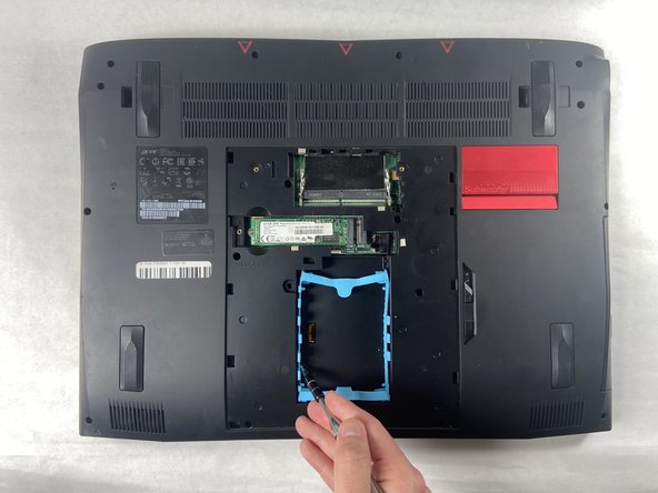
    • The service panel can be located on the bottom of the device. It is shown here as the panel located in the middle of the device, going from the upper vents to the bottom of the device.

  2. Acer Predator 17 G9-791 Motherboard Replacement: 手順 2、 2の画像 1 Acer Predator 17 G9-791 Motherboard Replacement: 手順 2、 2の画像 2
    • Loosen the two Phillips #0 screws.

    • Pull up slightly on the top of the panel to help fully separate the screws from the rest of the device.

  3. Acer Predator 17 G9-791 Motherboard Replacement: 手順 3、 1の画像 1
    • Continue pulling up on the panel to separate it from the laptop and remove it.

  4. Acer Predator 17 G9-791 Motherboard Replacement, Bottom Case: 手順 4、 3の画像 1 Acer Predator 17 G9-791 Motherboard Replacement, Bottom Case: 手順 4、 3の画像 2 Acer Predator 17 G9-791 Motherboard Replacement, Bottom Case: 手順 4、 3の画像 3
    • Remove the nine 4.5 mm Phillips #0 screws from the panel.

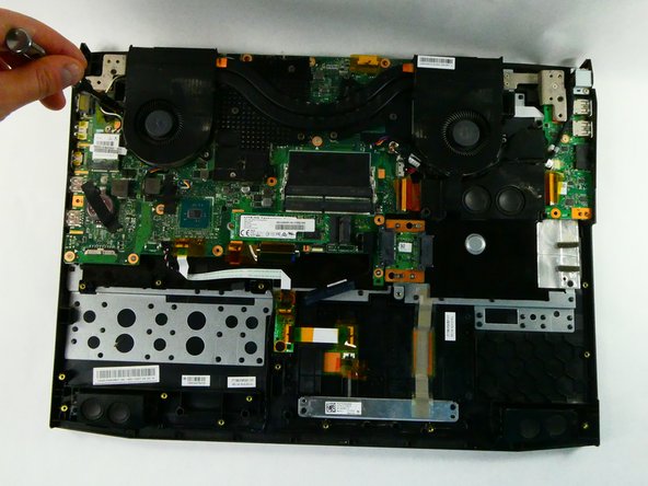
    • Remove four 14 mm Phillips #0 screws.

    • Remove six 7 mm Phillips #0 screws.

  5. Acer Predator 17 G9-791 Motherboard Replacement: 手順 5、 1の画像 1
    • Slide the "unlock" slider up located to the right of the service panel and pull the disc tray out.

  6. Acer Predator 17 G9-791 Motherboard Replacement: 手順 6、 1の画像 1
    • Remove the two 4.5 mm Phillips #0 screws located underneath the removed optical drive.

  7. Acer Predator 17 G9-791 Motherboard Replacement: 手順 7、 2の画像 1 Acer Predator 17 G9-791 Motherboard Replacement: 手順 7、 2の画像 2
    • Pry up on the edges of the bottom cover and lift the bottom case off of the device.

  8. Acer Predator 17 G9-791 Motherboard Replacement, Battery: 手順 8、 1の画像 1
    • Remove the six 4 mm Phillips #0 screws from the battery.

  9. Acer Predator 17 G9-791 Motherboard Replacement: 手順 9、 2の画像 1 Acer Predator 17 G9-791 Motherboard Replacement: 手順 9、 2の画像 2
    • Disconnect the battery connector from the motherboard.

  10. Acer Predator 17 G9-791 Motherboard Replacement: 手順 10、 1の画像 1
    • Gently lift the battery and remove it from the device.

  11. Acer Predator 17 G9-791 Motherboard Replacement, Fan Assembly: 手順 11、 2の画像 1 Acer Predator 17 G9-791 Motherboard Replacement, Fan Assembly: 手順 11、 2の画像 2
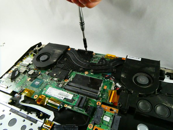
    • Remove the five 4.5 mm Phillips #0 screws located on the perimeter of the fans.

  12. Acer Predator 17 G9-791 Motherboard Replacement: 手順 12、 2の画像 1 Acer Predator 17 G9-791 Motherboard Replacement: 手順 12、 2の画像 2
    • Unscrew the six Phillips #0 screws enough to loosen the assembly from the motherboard.

  13. Acer Predator 17 G9-791 Motherboard Replacement: 手順 13、 3の画像 1 Acer Predator 17 G9-791 Motherboard Replacement: 手順 13、 3の画像 2 Acer Predator 17 G9-791 Motherboard Replacement: 手順 13、 3の画像 3
    • Detach the left fan's cord from the motherboard.

  14. Acer Predator 17 G9-791 Motherboard Replacement: 手順 14、 3の画像 1 Acer Predator 17 G9-791 Motherboard Replacement: 手順 14、 3の画像 2 Acer Predator 17 G9-791 Motherboard Replacement: 手順 14、 3の画像 3
    • Detach the right fan's cord from the motherboard.

  15. Acer Predator 17 G9-791 Motherboard Replacement: 手順 15、 3の画像 1 Acer Predator 17 G9-791 Motherboard Replacement: 手順 15、 3の画像 2 Acer Predator 17 G9-791 Motherboard Replacement: 手順 15、 3の画像 3
    • Lift the fan assembly up and out.

  16. Acer Predator 17 G9-791 Motherboard Replacement, Motherboard: 手順 16、 1の画像 1
    • Remove the two 5 mm Phillips #0 screws from the small PCB.

  17. Acer Predator 17 G9-791 Motherboard Replacement: 手順 17、 3の画像 1 Acer Predator 17 G9-791 Motherboard Replacement: 手順 17、 3の画像 2 Acer Predator 17 G9-791 Motherboard Replacement: 手順 17、 3の画像 3
    • Pull the small PCB to the right and then up to remove it from the device.

  18. Acer Predator 17 G9-791 Motherboard Replacement: 手順 18、 2の画像 1 Acer Predator 17 G9-791 Motherboard Replacement: 手順 18、 2の画像 2
    • Pull up on the “woofer” wire to remove it from its connector.

  19. Acer Predator 17 G9-791 Motherboard Replacement: 手順 19、 2の画像 1 Acer Predator 17 G9-791 Motherboard Replacement: 手順 19、 2の画像 2
    • Remove the two connectors.

  20. Acer Predator 17 G9-791 Motherboard Replacement: 手順 20、 2の画像 1 Acer Predator 17 G9-791 Motherboard Replacement: 手順 20、 2の画像 2
    • Separate the same two wires from the subwoofer.

  21. Acer Predator 17 G9-791 Motherboard Replacement: 手順 21、 2の画像 1 Acer Predator 17 G9-791 Motherboard Replacement: 手順 21、 2の画像 2
    • Pull the subwoofer up and out of the device.

  22. Acer Predator 17 G9-791 Motherboard Replacement: 手順 22、 3の画像 1 Acer Predator 17 G9-791 Motherboard Replacement: 手順 22、 3の画像 2 Acer Predator 17 G9-791 Motherboard Replacement: 手順 22、 3の画像 3
    • Remove the six connectors.

    • Some require you to flip the white part of the connector up first to remove them.

  23. Acer Predator 17 G9-791 Motherboard Replacement: 手順 23、 3の画像 1 Acer Predator 17 G9-791 Motherboard Replacement: 手順 23、 3の画像 2 Acer Predator 17 G9-791 Motherboard Replacement: 手順 23、 3の画像 3
    • Remove one 4.5 mm Phillips #0 screw from the WLAN card and pull the card out.

  24. Acer Predator 17 G9-791 Motherboard Replacement: 手順 24、 2の画像 1 Acer Predator 17 G9-791 Motherboard Replacement: 手順 24、 2の画像 2
    • Remove six 5 mm Phillips #0 screws from the motherboard.

  25. Acer Predator 17 G9-791 Motherboard Replacement: 手順 25、 2の画像 1 Acer Predator 17 G9-791 Motherboard Replacement: 手順 25、 2の画像 2
    • Turn the device around.

    • Use the black tab to disconnect the one connector on the bottom of the motherboard.

    • When reinstalling you should plug this connector back in as you set the motherboard down.

  26. Acer Predator 17 G9-791 Motherboard Replacement: 手順 26、 1の画像 1
    • Remove the two black 7 mm Phillips #0 screws from the left display bracket.

  27. Acer Predator 17 G9-791 Motherboard Replacement: 手順 27、 1の画像 1
    • Remove the two silver 5 mm Phillips #0 screws from the left display bracket.

  28. Acer Predator 17 G9-791 Motherboard Replacement: 手順 28、 2の画像 1 Acer Predator 17 G9-791 Motherboard Replacement: 手順 28、 2の画像 2
    • Pull the motherboard up and out of the device. You may need to open the lid slightly for the removal process.

    • When reinstalling the motherboard, ensure that wires do not get stuck under the motherboard as you set it back down.

終わりに

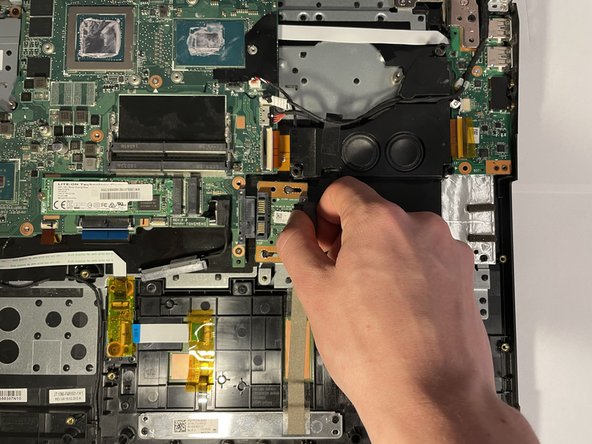
To reassemble your device, follow these instructions in reverse order.

作成者

4人の作成者と共同で作成されました。

Jimmy Coffey

メンバー登録日: 10/25/22

220 ポイント

1ガイドが承認済み

チーム

UMass Dartmouth, Team 5-1, Sinclaire Fall 2022 UMass Dartmouth, Team 5-1, Sinclaire Fall 2022人のメンバー

UMASSD-SINCLAIRE-F22S5G1

5 メンバー

7のガイドは作成済み

0 件のコメント

コメントを追加

統計データ:

過去 24時間: 0

過去 7 日: 3

過去 30 日: 37

今までの合計 699