このバージョンは誤った内容を含んでいる可能性があります。最新の承認済みスナップショットに切り替えてください。
必要な工具と部品
-
この手順は未翻訳です。 翻訳を手伝う。
-
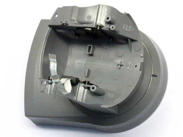
Gently lift the housing top, and slide it back while lifting.
-
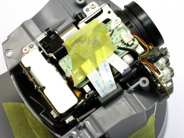
You will find the whole camera module wrapped in thick cellophane. For reasons of heat dispersal and prolonged life, I would recommend disposing of it during following steps. But only if your camera is for indoor use ! Outdoor cams might benefit from the wrapping, containing the heat in the camera module, preventing condensation/corrosion.
-
Optional : for reassembly, some adhesive tape might come in handy to hold down the flat cables.
-
-
この手順は未翻訳です。 翻訳を手伝う。
-
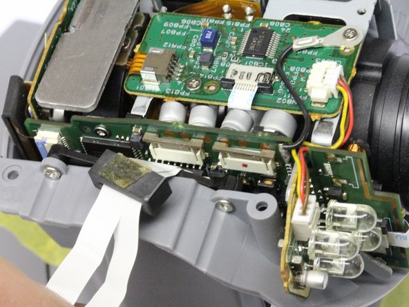
We will now disconnect the 2 flatcables that connect the camera module to the camera base.
-
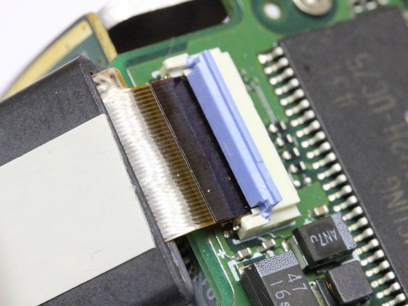
The ferrite core is attached to the left cable connector with some 2-sided sticky tape. Gently pry it loose so it can slide upward along the cables. Now is a good time to mark which cable goes in which socket.
-
The 2 brown/white cable connectors can now be reached. The brown part has to slide UP. Pry it loose with a very fine instrument : bit on the left, bit on the right, and repeat until loose. It should remain seated in the connector body. If it's no longer clamped, you're far enough ! FRAGILE !
-
Gently bend the ribbons to the side, so the camera module is exposed.
-
-
-
この手順は未翻訳です。 翻訳を手伝う。
-
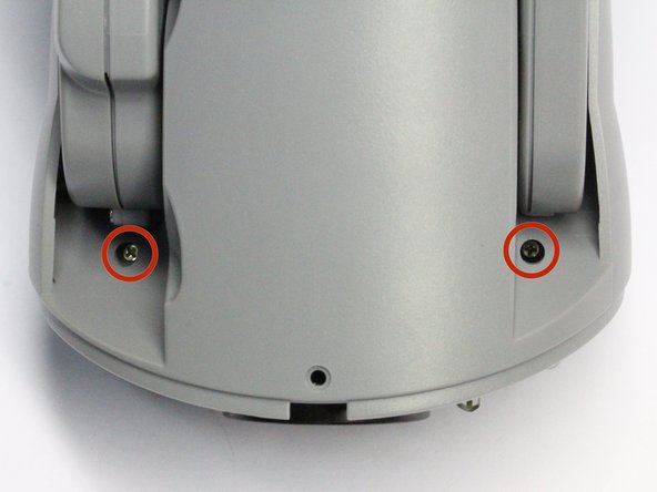
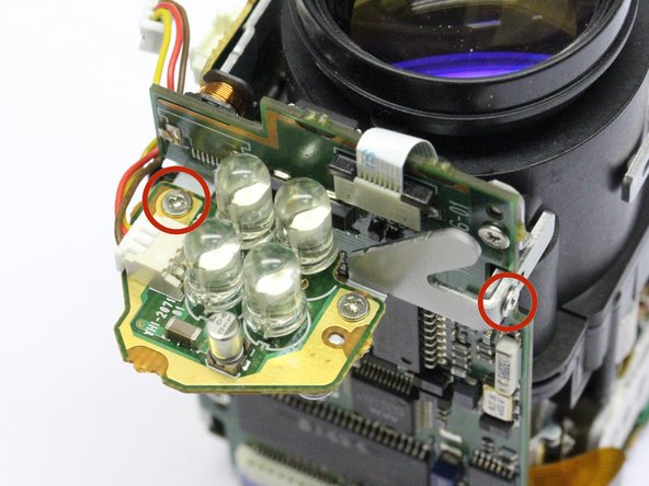
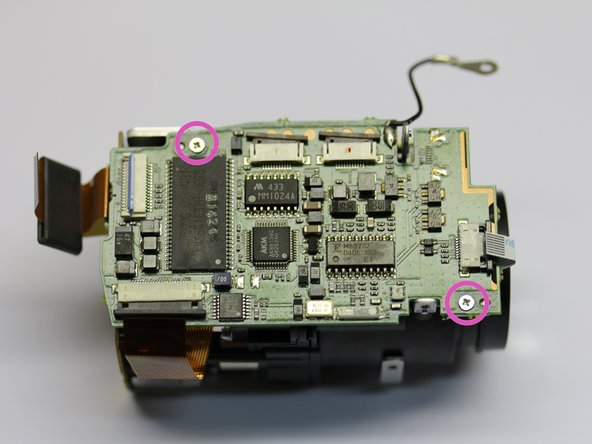
Take out the two screws holding the camera module to the plastic housing.
-
You can now lift the whole camera module straight up to remove it from the housing.
-
At reassembly, before tightening the screws, make sure the round plastic notches are well seated in the metal bracket's holes.
-
-
この手順は未翻訳です。 翻訳を手伝う。
-
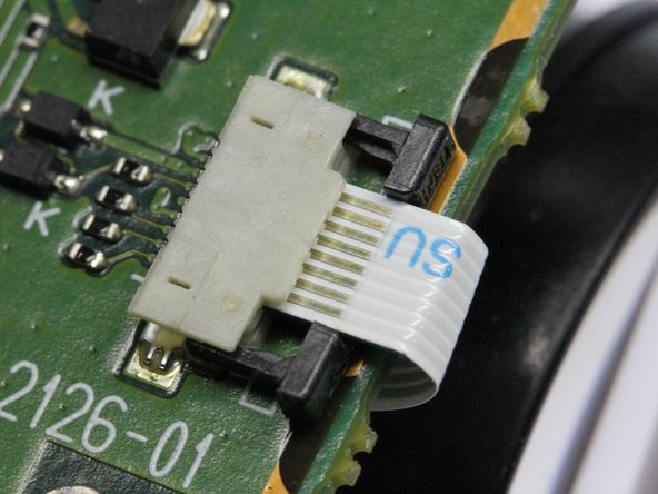
Disconnect the right ribbon cable. Hook your fingernails behind the right and left notches of the black connector part, and pull it towards the white ribbon cable with even and L/R balanced force until loose. FRAGILE ! The cable will slide out easily.
-
For reassembly : notice this cable is ON TOP of the black connector wedge. Insert the cable as intended, and push the black wedge back in place, again balancing force left and right.
-
-
この手順は未翻訳です。 翻訳を手伝う。
-
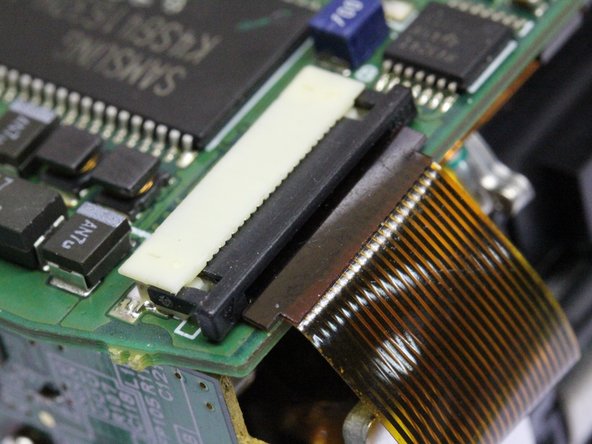
Disconnect the bottom left ribbon cable. Hook your fingernails behind the right and left notches of the black connector part, and pull it towards the brown ribbon cable with even and L/R balanced force until loose. FRAGILE ! The cable will slide out easily.
-
For reassembly : notice this cable is UNDER the black connector wedge. Put the cable back in place, and push the black wedge back in, again balancing force left and rigt.
-
-
この手順は未翻訳です。 翻訳を手伝う。
-
These are the capacitors to replace. PLAN in which order you will do the resoldering in the last step. Do it now, while you can still try all positions. Make sure your tip doesn't touch anywhere except on the spot where you want to apply the heat ...
-
To remove the old caps : use a pair of fine tipped cutting pliers, and cut the capacitors as low as you can. The bottom of the can is encased in a rubberlike material, and is easily removed using tweezers.
-
Then de-solder the capacitor's legs still attached to the circuit board. Provide a new clean patch of solder to the soldering islands.
-
Now install the new capacitors. Mind you, this is NOT to be done with your average soldering iron. You will need a 0,8mm tip or smaller, or SMD tweezers. And you'd better have darn good eyesight ... :)
-
Hint : soldering these caps is much easier with the black plastic seats removed from under them ... They are easy to crack open and discard.
-
Edit 7 jan 2016 : due to quite a few requests, I have assembled a few sets with these capacitors that I can send by mail. Just ask !
-
Edit 16 april 2017 : due to quite a few requests, a gain in experience, and several equipment upgrades, I have decided to offer a repair service. Just ask !
-


15 の人々がこのガイドを完成させました。
53 件のコメント
Always replace a capacitor with one of the same voltage or higher.
My supplier only offered 6,3v, and I believe that is the standard nowadays.
Do you or do you know anyone that will do the capacitor replacement once we have the board out for us?
No, sorry.
You could google “electronics repair (name of your city)”.
Lots of these tinkerers are becoming part of their local makerspace communities nowadays, so you could use this search-angle too.
Oh, and there's nifty guys to be found in small (!) radio/TV/satellite shops !
Success !