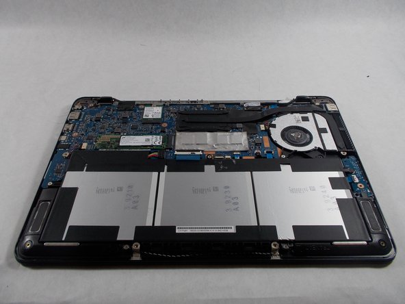
メインコンテンツにスキップ

ASUS Q324UA-BHI7T17 Power & Volume Button PCB Board Replacement

必要な工具と部品

  1. ASUS Q324UA-BHI7T17 Power & Volume Button PCB Board Replacement, Battery: 手順 1、 1の画像 1
    • Remove all 10 Phillips screws on the backplate.

    • All 10 screws are 0.55 inches and 20 mm in diameter.

  2. ASUS Q324UA-BHI7T17 Power & Volume Button PCB Board Replacement: 手順 2、 2の画像 1 ASUS Q324UA-BHI7T17 Power & Volume Button PCB Board Replacement: 手順 2、 2の画像 2
    • Carefully remove the backplate using the plastic opening tool.

  3. ASUS Q324UA-BHI7T17 Power & Volume Button PCB Board Replacement: 手順 3、 1の画像 1
    • Locate the battery near the bottom.

  4. ASUS Q324UA-BHI7T17 Power & Volume Button PCB Board Replacement: 手順 4、 1の画像 1
    この手順で使用する道具:
    Tweezers
    $4.99
    購入する
    • Next, lift up the battery connector from the laptop in the upper left side of the battery, using tweezers or spudger.

    • Make sure to complete this step with caution, because if the battery is not unplugged, the motherboard may shock you.

  5. ASUS Q324UA-BHI7T17 Power & Volume Button PCB Board Replacement: 手順 5、 2の画像 1 ASUS Q324UA-BHI7T17 Power & Volume Button PCB Board Replacement: 手順 5、 2の画像 2
    • Remove the six screws holding in the battery with a Phillips #0 screwdriver.

    • Once battery is lifted out and removed, proper dispose of the old battery.

    • Each screw is 0.5 cm in length and 0.5 cm in diameter.

  6. ASUS Q324UA-BHI7T17 Power & Volume Button PCB Board Replacement, Power & Volume Button PCB Board: 手順 6、 1の画像 1
    • Remove the screw holding the Power chip in place and remove it using a Phillips head #0 screw driver.

    • Screw length is 0.5 cm in length and 0.5 cm in diameter

  7. ASUS Q324UA-BHI7T17 Power & Volume Button PCB Board Replacement: 手順 7、 3の画像 1 ASUS Q324UA-BHI7T17 Power & Volume Button PCB Board Replacement: 手順 7、 3の画像 2 ASUS Q324UA-BHI7T17 Power & Volume Button PCB Board Replacement: 手順 7、 3の画像 3
    • Locate the ribbon connector connecting the power chip to the mother board.

    • Simply lift up the black component and the ribbon connector should be released, then the power chip should pop out easily.

    • Discard of the old power chip properly.

終わりに

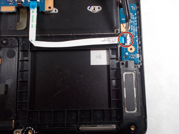
To reassemble your device, follow these instructions in reverse order.

作成者

2人の作成者と共同で作成されました。

Scott Santiago

メンバー登録日: 10/17/17

534 ポイント

5のガイドは作成済み

チーム

UMass Dartmouth, Team S1-G1, Simcock Fall 2017 UMass Dartmouth, Team S1-G1, Simcock Fall 2017人のメンバー

UMASSD-SIMCOCK-F17S1G1

3 メンバー

5のガイドは作成済み

0 件のコメント

コメントを追加

統計データ:

過去 24時間: 0

過去 7 日: 2

過去 30 日: 10

今までの合計 649