メインコンテンツにスキップ

ABXY/D-pad Conductive Sticker Replacement

必要な工具と部品

  1. ABXY/D-pad Conductive Sticker Replacement, Back Cover Removal Preparation: 手順 1、 1の画像 1
    • Before starting the disassembly, remove

    • The stylus

    • Any game cartridge

    • The SD card

  2. ABXY/D-pad Conductive Sticker Replacement, Back Cover Removal: 手順 2、 1の画像 1
    • Unscrew the four 6mm tri-point screws located at the four corners of the bottom panel.

  3. ABXY/D-pad Conductive Sticker Replacement, Case Separation: 手順 3、 2の画像 1 ABXY/D-pad Conductive Sticker Replacement, Case Separation: 手順 3、 2の画像 2
    • Be careful when separating the bottom panel from the front casing to avoid breaking the three cables connected to the motherboard (two on each side and one in the rear).

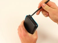
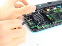
    • Using a spudger, separate the back panel from the front casing by gently prying around the panel.

    • There are many clips along the hinge of the case, so it is recommended to work your way along one short side and the two long sides before finishing the last short side.

  4. ABXY/D-pad Conductive Sticker Replacement: 手順 4、 3の画像 1 ABXY/D-pad Conductive Sticker Replacement: 手順 4、 3の画像 2 ABXY/D-pad Conductive Sticker Replacement: 手順 4、 3の画像 3
    • Using tweezers, disconnect the two cables that connect the rear buttons on either side to the motherboard by gently pulling them upwards.

  5. ABXY/D-pad Conductive Sticker Replacement, Battery Removal: 手順 5、 2の画像 1 ABXY/D-pad Conductive Sticker Replacement, Battery Removal: 手順 5、 2の画像 2
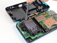
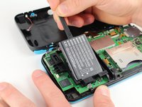
    • Using a spudger, lift out the battery.

    • Be aware that there is a sticky pad holding the battery into its tray. It may be necessary to use multiple tools to gently pry the battery away from the tray and motherboard.

  6. ABXY/D-pad Conductive Sticker Replacement, Motherboard: 手順 6、 2の画像 1 ABXY/D-pad Conductive Sticker Replacement, Motherboard: 手順 6、 2の画像 2
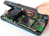
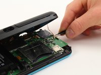
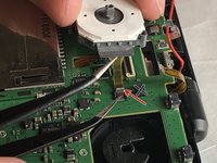
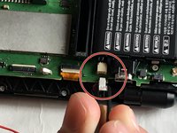
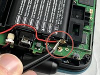
    • There are 8 ribbon cables that need to be removed as shown in the picture.

    • 2 of connectors (in green) are friction fit, unlike the rest of the connectors. Remove the cable by pulling it out gently. Do not attempt to open or unlatch these connectors in any way. Doing so will break them.

    • For the remaining 6 (in red), use a pair of tweezers to flip the latches up and pull the ribbon cable out.

    • Note that the second picture shows a broken ribbon connector next to the joystick ribbon connector (to the right of the red arrow). Do not attempt to unlatch this connector as shown in the picture!

  7. ABXY/D-pad Conductive Sticker Replacement: 手順 7、 2の画像 1 ABXY/D-pad Conductive Sticker Replacement: 手順 7、 2の画像 2
    • Unplug the following wires from the motherboard using a pair of tweezers.

  8. ABXY/D-pad Conductive Sticker Replacement: 手順 8、 2の画像 1 ABXY/D-pad Conductive Sticker Replacement: 手順 8、 2の画像 2
    • Remove the seven 4.4 mm screws using a J00 Phillips screwdriver bit.

    • Remove the motherboard from the device.

  9. ABXY/D-pad Conductive Sticker Replacement, ABXY/D-pad Conductive Sticker: 手順 9、 1の画像 1
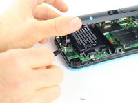
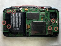
    • Flip the board over so the cartridge slot is on the bottom

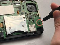
    • Peel off the damaged sticker and replace it with the new one

    • ABXY buttons

    • D-pad

    • If the new sticker doesn't fit properly, you can cut it apart and stick each pad down separately. As long as they're properly aligned and secure, the buttons will still work normally

終わりに

To reassemble your device, follow these instructions in reverse order.

ある他の人がこのガイドを完成しました。

作成者

1人の作成者と共同作成されました。

darth mango

メンバー登録日: 03/13/23

1,830 ポイント

3のガイドは作成済み

0 件のコメント

コメントを追加

統計データ:

過去 24時間: 7

過去 7 日: 21

過去 30 日: 99

今までの合計 1,067