この分解は進行中です。 – 最新版を見るには定期的に再読み込みします。
このバージョンは誤った内容を含んでいる可能性があります。最新の承認済みスナップショットに切り替えてください。
分解
この手順は未翻訳です。 翻訳を手伝う。
Flip the unit upside down to access the six screws on the bottom.
Remove the six screws indicated with a Phillips-head screwdriver. All the screws are of the same length.
Turn the unit back over, and pull the top half up and away from the device.
Unplug the laser assembly's power cable and ribbon cable from the main board.
Remove the two screws on the memory card/controller port, disconnect the ribbon cable, and lift it out of the case.
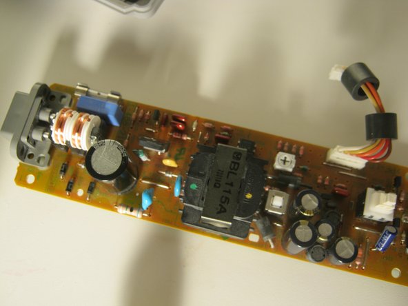
To remove the power supply, disconnect the cable and remove the two screws, then lift it out of the case.
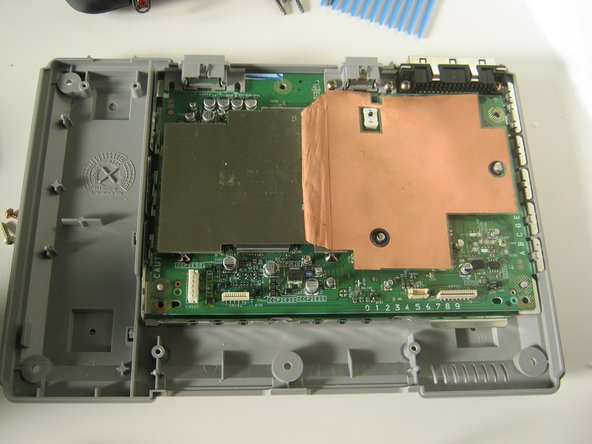
Remove the 3 screws from the shield.
Remove the 5 Phillips screws.
You can now lift the main board out of the case.
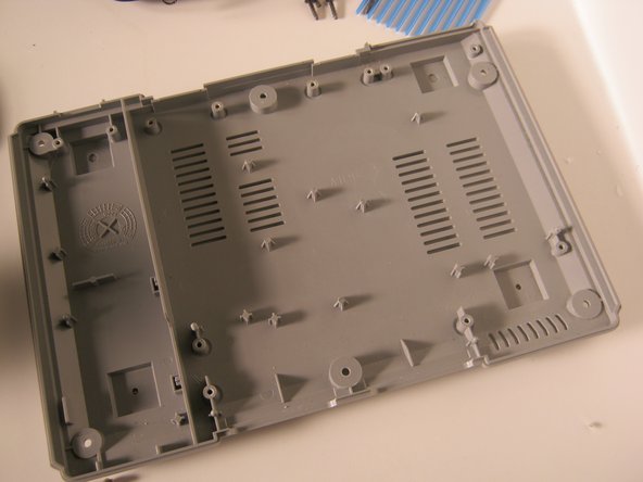
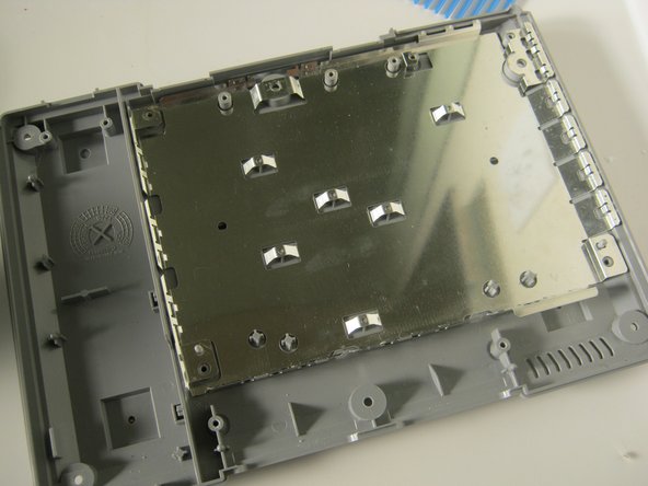
Lift the RF shield out of the case.
Reinstall the RF shield by dropping it in and lining up the slots and tabs.
Replace the main board. Only install the screws indicated in red.
Replace the top shield, and secure with the 3 screws indicated.
Reinstall the memory card / controller module. Connect the ribbon cable and replace the 2 screws.
Align the optical drive assembly with the three pegs.
Reconnect the power and data cables for the optical drive.
Slide the cover on the system in the same way you took it off and replace the black screws indicated.
Plug in the console and turn it on.
Thanks for looking at my teardown!
12人の作成者と共同で作成されました。
メンバー登録日: 11/10/09
89,116 ポイント
50のガイドは作成済み
バッジ: 55
+52 個以上のバッジ
Community
321 メンバー
1,490のガイドは作成済み
サイズを選択し、以下のコードをコピーして、このガイドを小さなウィジェットとしてサイト/フォーラムに埋め込みます。
過去 24時間: 1
過去 7 日: 8
過去 30 日: 36
今までの合計 43,065