はじめに
Direct drive turntables use sophisticated circuitry to control their brush-less DC motors. Over time these units can develop erratic speed issues due to leaky electrolytic capacitors, dirty contacts and potentiometers, cracked PCB solder joints, or faulty transistors and ICs.
In most cases, speed issues can be fixed by cleaning potentiometers and switches. If this does not resolve your issue and your unit is over 20 years old, you may need to “re-cap” it, which entails replacing old and leaky electrolytic capacitors with new ones of the same value.
If the speed issues still persist after cleaning contacts, replacing capacitors, and re-flowing cracked solder joints, you may have a faulty transistor or IC. This guide shows you how you can check and replace these parts as well.
必要な工具と部品
-
-
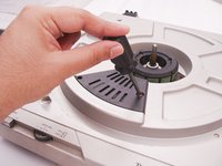
Simply lift off the platter with both hands and place it aside.
-
You may need push your fingers through the opening in the platter and push down a little bit to free the platter from the spindle.
-
-
-
If you have a belt-drive turntable, you will need to remove the belt off the motor spindle before taking off the platter.
-
Rotate the platter until the motor spindle and belt appear through the access hole, then gently pull the belt outwards with your thumb and lift off the platter without letting go off the belt.
-
Once the platter is off, release the belt, letting it rest around the platter inner pulley.
-
-
-
Remove the head-shell and cartridge as one unit.
-
Some units have a thumbscrew that must be loosend before the headshell can be pulled off.
-
Other types use a socket-type connector. Loosen it and gently pull the headshell ff
-
After removing the headshell, make sure that the tonearm is firmly locked in its rest.
-
-
-
-
Simply loosen the counterweight until it falls free off the tone-arm.
-
Be sure to take note of the tracking force setting before removal if you do not have the specification for your cartridge. You will have to reset this tracking force after reassembly and re-balancing of the tone-arm.
-
-
-
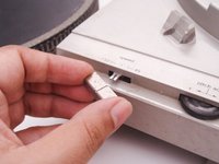
Pull the plastic caps off any slide or push-button switches and keep them aside.
-
Also remove any trim pieces such as access covers for adjustments.
-
-
-
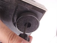
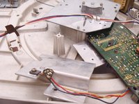
Put the dust cover back on and turn the turntable upside down. Unscrew the fasteners holding each of the rubber feet to the base plate.
-
Then remove any remaining screws holding the base plate onto the plinth. The base plate can now be lifted off to reveal the internals.
-
You may need to wedge a flat-blade screwdriver between the plinth and base plate to lift it off.
-
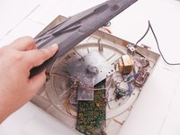
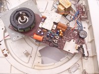
You can now access the motor, power-supply, and main circuit board for repairs or servicing
-
-
-
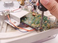
You may need to remove the PCB to facilitate easier access to various components.
-
Remove any screws holding the PCB to the chassis, plinth, or to any heat sinks that would restrict removal.
-
Disconnect any cables from the control PCB to other parts of the turntable such as the speed selector switch and power supply. On some models, such as this Technics, you may need to cut the wires if no connectors are used.
-
You can now rotate or remove the PCB.
-
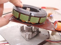
On many direct drive models, the motor's stator coil is soldered onto the control PCB. The motor's shaft and bearing assembly, along with its back plate may also be held onto the PCB by long screws threaded through the stator assembly. In this case, you can remove the PCB with the shaft and bearing assembly and back plate attached.
-
-
-
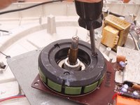
Rotate the control PCB along with motor assemblies, to access the screws on the top of the motor's stator assembly.
-
Remove the long screws threaded through the stator assembly into the shaft and bearing assembly.
-
You will now be able to separate the shaft and bearing assembly from the control PCB.
-
-
-
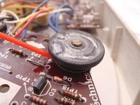
Identify the trimmer potentiometers and spray thoroughly with contact cleaner. Use an appropriate screwdriver to turn the the potentiometer position back and fourth vigorously for a bit. This helps remove any dirt or oxidization.
-
Spray any push or slide switches with contact cleaner and operate them vigorously.
-
Let the board sit for a while, then reassemble the turntable and check for steady speed. If the speed is till unstable, or if you are not able to get a correct speed for 33 and 45rpm modes by adjusting the trimmer potentiometers, proceed further with this guide.
-
-
-
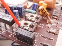
Inspect the PCB for any solder joints that look suspect. This includes cracked joints, evidence of shorts or burnt traces, bodged repairs by previous owners, etc..
-
Example of cracked solder joints.
-
Evidence of shorting, and botched repairs that may need to be redone.
-
Re-solder any joints that appear suspect. If a component such as a resistor is obviously burnt, replace it with one of a similar value.
-


To reassemble your device, follow these instructions in reverse order.
ある他の人がこのガイドを完成しました。