メインコンテンツにスキップ

2018 model Internal part number: HE500S5U51

4回答 すべてを表示

My Hisense 50R6E won't turn on.

About 2 weeks ago my Hisense 50R6E stopped working, I had some LED strip lights running along the back that were plugged into the USB slot so they would turn on and off with the TV. I fell asleep watching TV and woke up the next morning and my picture was black and the lights were flashing like crazy for 3 seconds then would stop for 2-3 seconds and would repeat. So I unplugged the strip lights and tried to turn my TV on and it didn't work, dark black screen and the red input light just flashed about 3-4 times. I tried power cycling the TV to no avail, I also changed cords and made sure the cord was good, made sure the outlet was good, made sure no breakers flipped. So I then ordered a replacement main board same exact part number and replaced that and still did not work. I then order a new power board same exact part number and it still has not worked. I looked up several video of what I should test with a multimeter to make sure the connection between the main and power is good and everything seems to be testing okay. I have now ordered a tcon board same exact part number hoping that will be it because if I replaced the main, power, tcon what else could it be besides the back lights? Which i also already ruled out because if it was just backlight I would still hear sound and the tv would still turn "on" but I hear no sound and I can't take control of it with my roku remote app on my phone which means it's not turning on and connecting to the registered WI-FI. Please any help or information anyone can provide would be GREATLY APPRECIATED.

Block Image

Block Image

Block Image

Block Image

Block Image

Block Image

Block Image

Block Image

Block Image

Block Image

Block Image

Block Image

Block Image

Block Image

Update (03/23/24)

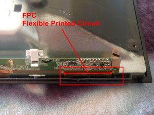
I have it torn down so I can see what exactly is going on with the LED lights. But you'll have to forgive me this is my first project like this and I

Block Image

am most certainly a novice just trying to learn as much as I can. I am worried about these small driver panels at the bottom so I can get to everything, is there anything I need to worry about NOT doing right here? And this metallic looking tape do i need more on hand to put more down when I'm sealing everything back up or? And if I do what is it called so I can get some?

The black goo that I am referring to is stuck ONLY behind each of the lights onto the metal of the TV.

Block Image

Block Image

I am also looking for replacments right now and can only find 2 different kinds. 1 is sold as exactly what I have in the tv with no split in the middle standard 4 pc. Then the other is an 8 pc that looks like it is separated and plugged in again in the middle? Why is that, do you know? And does it really make a difference in quality/ life of product/ or installation difference? The 4 pc is like 60 bucks the 8 pc is 20 thats why I am asking, I have kinda learned you get what you pay for and I don't wanna throw cheap LEDs in there just to have this problem again in a year or 2.

Block Image

Block Image

この質問に回答する 同じ問題があります

この質問は役に立ちましたか?

スコア 1
6 件のコメント

@ericreyes59663 yes, there are strips that clip together. I do agree. I try and purchase mine from reliable sources if they have them available. I do try and stay away from alibaba and ebay since I have had bad luck on those. Of course that is just my personal opinion

さんによる

Just wondering if there is any major difference in the quality between the ones that clip in the middle and the ones that dont because there's a serious price difference.

さんによる

@ericreyes59663 are they advertised to fit your panel? If so, give them a try. It is for your own TV so if they go on the fritz in a year or two it is okay since you know how to replace them again. I am just a bit more careful since I repair TV's as a hobby for friends and family etc and do not want them have to go through this again :-)

さんによる

I believe so they have the exact same product number i guess? The CRH-BX50S1U923030T041288V-REV1.1

I tried to put batteries in a series with wire and got it to test on the multimeter at 3V but when I was connecting it to the + and - on the lights I wasn't getting an reaction at all but i wasn't sure if this is just due to poor connection due to a rigged tester or if just EVERY single light went out, its seems very unlikely that every single light went out so I'm thinking I have poor connection and should order an actual backlight tester :/ theres another 20 bucks.

さんによる

@ericreyes59663 I think you are already past the backlight tester. that is something you use before your take it all apart. Save the money on that end and use it to invest that in new strips :-)

さんによる

1以上のコメントを表示

コメントを追加

1 件の回答

最も参考になった回答

@ericreyes59663 let us know if have you taken any voltage measurements on your TV? Now where you have replaced all teh boards, the only thing left is the panel. However, you really should not have gotten the behavior of your USB strips. Post some good pictures of you boards as well as the driver boards. Those are the long skinny boards that connect directly to the LCD panel. Include the ribbon cables in any image. I suspect that this is where the issue originates.

iFixitでの質問に画像を追加する方法

Update (03/21/24)

@ericreyes59663 two things come to mind. The backlights and the LCD panel. For now try this:

  • Unplug the power cord at the power board
  • Remove one ribbon cord (image 9) from your driver board
  • Replace power cord on power board
  • Turn TV on

Let us know what is going on with your TV. Next repeat, just this time the other side.

  • Unplug TV
  • Replace previously removed ribbon cable
  • Disconnect the other ribbon cable.
  • Reconnect the power cord
  • Turn TV on

Let us know what is going on with your TV. If this is a bad panel, separating the Left and Right half sometimes shows results (like that half the panel will light up or blink.

Next, reconnect everything on your TV. Now use a voltmeter and set it to something like 300 VDC or similar. Connect the black probe from your meter to ground and turn your TV on. Now measure the voltage on your LED backlight connector. It's either the Red that is + or the White. Let us know what that voltage is. You may need to have your meter already connected when you turn you TV on. Let us know what you find out.

Looks like your power board only has one line in to the backlight. That means that all of your backlight strips are in series. If a single LED is out, the backlight will not come on. Some TV's have a special circuit that "checks" the backlight. It they do not come on (do not draw any power) the TV will not function. It goes into a protect mode. That would also mean that you would not have any sound. For now, you can't rule out the back lights

Word of caution. While your TV is plugged in and turned on, your power board receives full household power (110V) You need to be mindful where you place your hands and fingers. Do not touch anything with your bare hands and stay away from the "Hot Side". That also goes for when you turn your TV off. The capacitors remain charged and they do "bite" if you get in touch with the contacts :-) Not a pleasant experience.

Update (03/23/24)

@ericreyes59663 that is the crux of the thing.

Block Image

Those are FPC or Flexible Printed Circuit's They are fastened to the LCD via a special process. Take a look at something like this video about how it is done.

You do want to avoid those boards (FPC) from coming off. Whenever I work on a LCD panel, I secure those boards to the panel with some painters tapes or similar.

Also, those driver boards always correspond to the T-con board. Check on here and that is just based on the number on your driver boards.That is how things get matched up and that is why we can't just pop in another panel. They do have to match. If we could change those driver boards then we could just use any panel and a matching T-con board. Companies would not like that. It'll cut into their profit.

I do hope this answers what you were asking :-) No forgiving necessary. We are all in this together. We are all learning and sharing. Can't learn if you don't ask :-) Remember what's important:

Repair is War on Entropy !

このアンサーは役に立ちましたか?

スコア 1

19 件のコメント:

Yes as I said I tested the boards and as far I can tell they seemed fine I also tested the ac cable to the tv and the socket socket tested at about 125v the ac cord tested at about 125 v which it is a 10amp 125v so the ac cord is good, the pins I tested, tested at 12v like they were labeled others tested at about the 3v like they were labeled. And what do you mean by the panel what is that? And okay I will upload pics first thing in the morning im about to head to bed where I live. Thank you for the reply.

さんによる

@ericreyes59663 The LCD panel can be the culprit. I just always hope that we measure the voltages that the powerboard supplies and the main board regulates. It gets expensive to just replace the boards. Measure the voltages on your T-con board and the outputs. If you post some images of it, we can hopefully point out where and what voltages to measure.

さんによる

I I have uploaded the pics. I think I got everything you asked for let me know if I missed any. Also is the LCD panel just the screen?

さんによる

@ericreyes59663 the driver boards are considered part of the screen since they are attached via a special procedure. In general, yes LCD panel is the screen. Let me see what I can find out on your boards.

さんによる

So you are guessing it is the ribbon cables or the actual screen?

さんによる

14件以上のコメントを表示

コメントを追加

回答を追加する

Eric Reyes さん、ありがとうございました!
統計データ:

過去 24時間: 0

過去 7 日: 7

過去 30 日: 27

今までの合計 125