メインコンテンツにスキップ

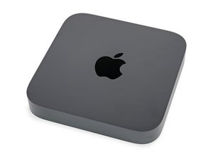
長く待ちわびた人気モデルMac miniの最新モデルです。プロセッサはオプションで3.6 GHz quad-core Intel Core i3、3.0 GHz 6-core Intel Core i5もしくは3.2GHz 6-core Intel Core i7プロセッサから選べます。

85回答 すべてを表示

2018 Mac mini won't turn on

Hi all

Already had another working 2018 Mac mini, so I switched the logicboard, so to test the power supply......the already working Mac mini still turn on with the psu of the system that doesn't turn on, so the psu is not the problem, tried the bad system with the psu of the one that's operational...still nothing...no light, no sound, just completely dead......also tried the fix for systems that shows same symptoms after an update (T2 restore steps with Apple Configurator). still don't see the system......so I am inclining myself to a bad chip somewhere in the logic board.....is there any basic troubleshooting steps that I can use to measure transistors continuity or any other steps that anyone is aware of...thanks!!
この質問に回答する 同じ問題があります

この質問は役に立ちましたか?

スコア 3
1件のコメント

Mac minis are a bit trickier to find data on that MacBooks or iPhones. Or even iMacs to be honest. There are definitely things to try, but I will have to look in the morning. This is mostly a reminder to myself to check to see if I even have info for this model. And where stuff to check might be located.

さんによる

コメントを追加

2件の回答

最も参考になった回答

First thing's first. I would give the logic board a thorough once over. Check and see if anything just looks bad. Feel free to add some pictures to your original post.

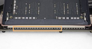
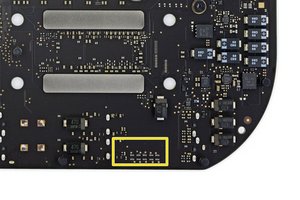
I assume by the fact that you're not getting it to detect in DFU mode, that it's not powering in at all. This is a board I don't have a ton of experience with honestly, but based on the schematic, there are some debugging LEDs that were likely present during production, that probably aren't on the actual board. They are similar to the LEDs used in an iMac for diagnostic purposes. You man be able to make use of the pads, regardless of the presence of the components, but I want to know what's actually there first, since I cannot tell from this picture. They're located along the edge of the board, by the RAM modules.

Block Image

EDIT:

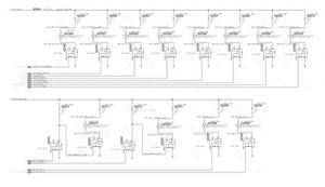
Based on further looking, I suspect all this stuff is blank. Because all the mosfets on the bottom, looked blank. But, those could likely still be used to check vital system rails. You would just have to use the mosfet pads, since that's what would let current through to the LEDS. That aren't there. Some of these also feed into each other. But you can check for incoming voltages, or shorts to ground on the mosfets since the traces that feed them will still be there.

Block Image

このアンサーは役に立ちましたか?

スコア 1
コメントを追加

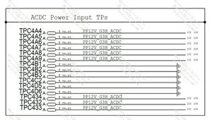
@flannelist just out of curiosity, why wouldn't you check the TP for the 12V ACDC power when it is connected? I was thinking something like this

Block Image

to check PP12V-G3H_ACDC.

You were of course right about the debug LED's

Block Image

このアンサーは役に立ちましたか?

スコア 1

1件のコメント:

You could do that too. Depends I suppose, on how far down into the system the issue is, but that's perfectly valid. And is probably a good idea, regardless. To check and see if power is even getting into the system.

さんによる

コメントを追加

回答を追加する

Macmod さん、ありがとうございました!
統計データ:

過去 24時間: 0

過去 7 日: 4

過去 30 日: 26

今までの合計 291