メインコンテンツにスキップ

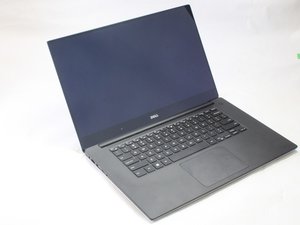
"The worlds smallest 15.6-inch laptop packs powerhouse performance and a stunning InfinityEdge display all in Dell's most powerful XPS laptop."

56回答 すべてを表示

How can I chage my power adapter on the motherboard of my xps 15 9550?

My xps 15 9550 no longer charges, but the charger seems fine, I think it is the power adapter which needs to be changed, is there a step-by-step video to do this? thank you.

回答がありました! 回答を表示 同じ問題があります

この質問は役に立ちましたか?

スコア 0
コメントを追加

1 件の回答

ベストアンサー

Hi,

No video but here’s the service manual for the laptop that will help.

Go to p.65 to view the necessary pre-requisite steps and then the procedure to remove/replace the power adapter port (aka DC-In jack - supplier example only).

There are other suppliers online that may suit you better. Just search for Dell XPS 9550 DC-In jack to get results

このアンサーは役に立ちましたか?

スコア 2

7 件のコメント:

thank you!!!

さんによる

You can't go by "seems fine". Did you measure the voltage on the adapter connector? When unloaded (not plugged in) it should be somewhat higher than what is written on the adapter. If it is, and doesn't change when you move the wire around, the when yu open the computer up, carefully inspect for bad solder connections on around the connector b4 removing/replacing it.

さんによる

@ruggb

Might be easier to use an Ohmmeter and measure between the input to the socket and the socket's output connections on the cable plug.

A lot of the time, the inner conductor breaks internally in the connector so the +ve leg is open circuit.

Cheers

さんによる

@jayeff I didn't follow that? The "socket" is on the computer, the "plug" is on the cable. The socket's output connection would be on the PCB. If the connection is broken in the connector and the +ve leg is open then measuring voltage on the adapter connector (plug) would be the easiest. Or maybe I confused you with "adapter connector"?

さんによる

@ruggb

if you click on the link in my answer above showing the power adapter port (HP's name for power port in laptop) you'll see there is a cable attached to the socket connector. It is not hard mounted on the board, it plugs into the board.

So connecting an Ohmmeter between the input side of the socket connector i.e. centre pin, and the red wires on the socket connector's cable plug and then between the outer ring of the socket connector and the black wires will prove continuity through the socket connector for both +ve and -ve leads.

さんによる

2件以上のコメントを表示

コメントを追加

回答を追加する

Carl Hooppell さん、ありがとうございました!
統計データ:

過去 24時間: 0

過去 7 日: 0

過去 30 日: 2

今までの合計 173