メインコンテンツにスキップ

Logitech(ロジクール)のワイヤレスおよびコード付きコンピュータマウスの修理ガイドとサポートです。

275回答 すべてを表示

Fixing destroyed solder pads

Hello I attempted for the first time to desolder and attach some new switches. Things did not go well… I thought a fix would be to follow this guide: https://www.instructables.com/How-to-Rep...

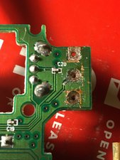
Upon completion there was still no contact with both M1&M2; here are the photos after I cleaned up.

Block Image

Block Image

In the first photo as you can see I attempted to cut the excess copper before solder, not sure which method would have worked better considering the copper adhesive would move even after being heated which was expected.

My primary questions I suppose would be in photo 1 am I suppose to match the adhesive exactly to size or can I have some excess laying on the PCB? Am I also to clean more thoroughly? I used 97% isopropyl with electronic swabs. The soldering wire has flux so I didn’t apply any flux paste which came with my kit.

In photo 2 am In trouble with the trace? I should also ask if my method would even work using 5mm copper adhesive.

P.S. I can make an additional thread for this but I tried the same method as well on my Celeritas keyboard

Block Image

and had no function with the switch I used?

What’s the deal? Thanks for reading and any help!

この質問に回答する 同じ問題があります

この質問は役に立ちましたか?

スコア 0
コメントを追加

1 件の回答

最も参考になった回答

Hi @kembaw ,

To me the problem is how to mount the switch so that it remains secure and doesn’t come loose rather than how to electrically connect it to the circuit board.

I would try gluing it to the board (neutral cure silicone sealer perhaps) and hopefully there is enough excess connection tails from the switch showing through on the solder side so that you can run insulated wires from them to where the pads that they should’ve connected to first make contact with another component and solder the insulated wire to that point i.e. bypass the faulty pad and track so that the switch is wired directly to the next point.

Here’s an image showing what I mean from the last image that you posted.

Block Image

(click on image to enlarge for better viewing)

このアンサーは役に立ちましたか?

スコア 1

3 件のコメント:

Hey thank you for your response. If I'm prioritizing mounting the switch instead of insuring electrical connectivity; is the process the same with the mouse PCB? I was under the impression the trace is on the right side center hole and ensures connectivity between both buttons.

If I understand you correctly you're saying use a glue to hold the switches as far as I can and then come in with an insulated wire to any contact point on the board and it should work?

Would the process be similar to this video? https://www.youtube.com/watch?v=ref9JHUf...

Any recommendations for both glue and wire?

I was thinking 40 AWG magnet wire but I don't know where to start for a sealer... Perhaps ShinEtsu KE-45 RTV?

I was trying to keep this as low cost as possible, but I'm reaching that point where I could just replace the mouse. Although I value the learning experience here it seems I'm out of my depth once I made the simple mistakes that I did.

Anyways thank you for your help.

さんによる

One more question if I may; why didn't the copper adhesive work?

さんによる

@kembaw

Don't know much about the copper adhesive as I never tried it.

As for the glue i just go with something like this which I have around the house just for when I needed to seal gutters or shower recesses etc.

It is usually strong enough and is also non conductive. The downside is you have to be patient and let it cure properly i.e. sometimes 12-24 hours before touching it again. Read the label on the product

40 gauge wire seems a little thin. Again I just use what I have to hand. I have a old length of Cat 5 ethernet cable (telephone cable would also do as it is about the same gauge) that I use for any spare wires as it has 24-28 gauge (not sure but somewhere in this range) insulated wires and I just cut one wire out of it, the length that I need

It may be easier if you solder the wire to the appropriate switch lead first, poke the wire through the hole then apply the silicone and press it down and maybe put some sort of weight (heavy object?) on it to hold it it place until it cures. If the body of the switch touches the board you can use the glue to hold the body as well as it pushing through the holes etc. If it squashes out when the switch is pressed into it then it is easy enough to cut it away with a safety razor blade when it has cured to make it look neat but it won’t be seen anyway and may add to the holding strength if left there.

After it has cured then it is easy to connect the other end of the wire to a suitable point. Make sure that you have plenty of wire connected to the switch first so that you’re not left short when trying to find the nearest connection point. Being insulated the wire can be run direct line of sight over the other tracks etc if necessary as it won't be seen when everything is closed up

さんによる

コメントを追加

回答を追加する

Will さん、ありがとうございました!
統計データ:

過去 24時間: 0

過去 7 日: 2

過去 30 日: 20

今までの合計 833