メインコンテンツにスキップ

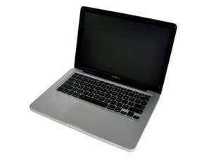
2012年半ばモデル、A1278/2.5 GHz i5または2.9 GHz i7プロセッサー。

1623回答 すべてを表示

How to determine which components i.e. resistors, diodes are what?

Hi so I got this Macbook Pro for free and it has some water damage. It still turns on but only when plugged in. It turns off when it unplugged and does not see a battery nor does it work with a charged good battery in it. What I wanted to know is how can I identify what component I am trying to test whether it be a resistor capacitor or anything like that. I know what they look like traditionally but I'm having a bit of trouble identifying it on the Mac specifically. Also if you could tell me what to look for when testing these various components with a multi meter, in general terms. Like a resistor is bad or shorted when your multimeter beeps when set on continuity (not sure if that correct) with one prong on negative and the other on positive. I have the schematic. If you have any suggestions specifically to the water damage that would be awesome but not necessary.

The board number is 820-3115-B and its EMC NO.:2554. Model A1278

Thank you for your time
この質問に回答する 同じ問題があります

この質問は役に立ちましたか?

スコア 1
コメントを追加

1 件の回答

最も参考になった回答

Jim, you cannot identify those by looking at it like in the good old days. You will need the schematic and a board layout to determine what component you are dealing with. "multimeter beeps" will only verify continuity but not if a resistor is working (you need to set your multimeter to ohm's and check the value of the resistance against the one listed in your schematic. Capacitors can have continuity but wrong capacitance, you need a meter for that. Now, (here comes the but) there is a tool (comes in very handy) which are "Smart Tweezers" like this one. I've found this to be an invaluable tool to identify SMD components.

Update (03/21/2016)

You are right. I obviously did not get that you "just wanted to know how to visually identify different components". You cannot visually identify the components

このアンサーは役に立ちましたか?

スコア 3

3 件のコメント:

I don't think you understood correctly I have a multimeter I have a schematic I have a board view. With the board view though I still have trouble finding things so I just wanted to know how to visually identify different components. Also when I said put it onto continuity and place one probe blah blah blah I was just using that as an example of the kind of info I was looking for not as a fact thanks again

さんによる

So you can't look at the MOSFETs on there and tell that there MOSFETs or look at fuses on there and tell there fuses etc. And how do you know when thing like resistors transistors fuses are bad how do you teat them and what do I look for

さんによる

You need to use your schematic, board layout diagram and your multimeter to check your components as described in my original answer. Ohmmeter for resistance , capacitance meter for capacitors and transistor tester or oscilloscope for the mosfets and coils.Fuses are best checked by continuity testing with your multimeter. I tried to explain this in my answer but you expressed that I did not understand you correctly and " just wanted to know how to visually identify different components. "

さんによる

コメントを追加

回答を追加する

Jim さん、ありがとうございました!
統計データ:

過去 24時間: 0

過去 7 日: 0

過去 30 日: 2

今までの合計 913